Contact-free high-speed data transmission
Posted: 3 December 2008 | | No comments yet
This paper deals with a solution to the problem of transmitting on-board information between railway cars connected by means of automatic couplers.
This paper deals with a solution to the problem of transmitting on-board information between railway cars connected by means of automatic couplers.
The collaboration between mechanical and electrical engineers often results in a fascinating challenge. This paper deals with a solution to the problem of transmitting on-board information between railway cars connected by means of automatic couplers.
Some important requirements need to be considered:
- Cost savings through reduced number of electrical contacts
- High reliability in rough environments
- Electromagnetic compatibility (EMC, emissions and immunity)
- Future applications with high data transmission rates
Initial situation and state-of-the-art
Scharfenberg® railway couplers were established in 1903 and have proven their value as market-leading systems, with more than 300,000 couplers delivered. Figure 1 shows the functional principle of a modern coupler, whilst Figure 2 on page 72 shows a photograph.
Bridging data communication between railway cars is rather complex and expensive using current state-of-the-art technology. A large number of control signals for various train facilities need to be transmitted, requiring many electrical contacts. Depending on the design and the version of the train, the electrical heads can host more than 100 contacts. These contacts must have a very small transfer resistance, for example using a jack-pin combination.
Regarding the extended life-cycle, the large number of coupling procedures and possible adverse environmental conditions and heavy pollution, only high-quality materials and designs can be used. In addition, a large amount of extra data has to be transmitted, both for control tasks (e.g. via the wire-train bus) and passenger entertainment and information purposes (e.g. audio and video services). Current solutions include expensive coaxial cables and connectors.
Aspects of technical innovations and cost savings determine the enhancements, so that an advanced, contact-free design is the answer to many problems.
Comparison of technical solutions
In order to compare and evaluate suitable technical solutions, mechanical and electrical aspects as well as production requirements have to be considered. From the possible alternatives, these include:
- Infrared transmission
- Optical transmission
- Inductive coupling
- Short-range radio transmission with microwaves
The most promising version should be chosen.
The data rates that can be achieved using the inductive coupling method are too low regarding the increasing data transmission demands, although the other properties would be sufficient.
The use of a high-frequency application seems evident. The microwave range of frequencies, encompassing several GHz, looks very promising, with the additional advantage that new, specific components can be developed. In contrast to the microwave solution, the infrared and optical transmission solutions have disadvantages with respect to mechanical properties and are susceptible to pollution problems. Direct links between the railway cars using off-the-shelf wireless local area networks are not considered as they do not fulfil reliability, noise immunity and tap-proof requirements.
Important aspects
In order to determine a technical solution as well as to investigate and develop the desired transmission system, the following aspects have to be considered:
- Reducing the number of electric contacts in the coupler
- Developing a robust transmission system for the rough railway environment
- EMC conformity
- Simple mechanical design
- Coupling with on-board data bus systems
- Extension possibilities for increased data transmission rates and bandwidth requirements
Test set-up and typical measurements
The following measurements have to be carried out to determine essential parameters of the transmission system:
- Input impedance, reflection factor and directional characteristics of the developed microwave antennas
- Attenuation and received power of the transmission channel using an antenna pair,
- Cable attenuation for the selected frequency range
- Estimation of the required transmitted power
- Radiation characteristics (measured electrical field strength at a given distance)
- Noise immunity (external field generation)
Technical implementation
The implementation of the chosen solution includes the use of microwaves with a data transmission rate of 40 Mbit/s, higher rates are optional. The working principle of the transmission system is shown in Figure 3 on page 72. A key part of the system is the antenna pair, with specific properties matching the chosen frequency range and the dimensions of the coupler. The antennas are connected to transceivers via HF-adapters and low-loss coaxial cables. Transceivers are devices that can be used as transmitters and receivers (bi-directional transmission).
A number of investigations and tests were necessary in order to establish the system and check if all requirements were fulfilled. These tasks are listed below:
- Development of special control software to detect possible transmission failures
- Transmission tests with frequency-dependent characteristics on the one hand and reception of large amounts of data on the other hand
- EMC tests checking the immunity of the transmission channel by generating narrow- and broad-band signals
- Checking field-related radiations
The permitted electrical field-strength values for the GHz range have not been decided upon yet. However, a decision is expected for the future. In any case, mutual interferences between different transmission systems must be prevented, e.g. in case of two trains passing on parallel tracks.
Some frequency-ranges are open for public use, examples are shown in Table 1.
Of course, the named transmission channels can often be used for test purposes in order to allow an easy estimation concerning the performance of the system.
Restraints to be considered are given by the maximum allowed power of the transmitters. The result of a typical measurement with a Vector Network Analyser is shown in Figure 5 on page 74, where the transfer characteristic of the transmission system with a pair of specific microwave antennas has been plotted depending on a frequency between 3 and 6 GHz. The appropriate function is defined by S21*=10·log(Pr/Pt) dB=Pr*-Pt*.
Pt being the transmitter power and Pr being the received power. A typical value is given by a power of Pt*=15 dBm with relation to the reference of 1 mW, therefore Pt=31.6 mW.
Figure 5 on page 74 shows that the performance of the designed antennas is quasi-unrelated to the frequency, which is a very advantageous property. Assuming a value of e.g. 45 dB with reference to Figure 5 on page 74 and adding some dB to compensate for the unavoidable losses of the connected cables with required lengths, we end up with a receiver power level approximately Pr*≈-30 dBm, Pr≈1 μW. This shows that we have ample resources to create a reliable transmission system with sufficient signal-noise-ratio.
Application and conclusions
Different classes of signals have to be considered with regard to the integration of the microwave transmission system into the on-board control facilities:
- Signals for train protection and control
- Signals of the train bus
- Passenger information and entertainment
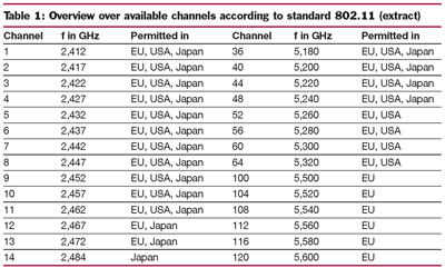

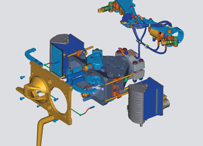

Figure 1: Main components of a Scharfenberg One4 coupler
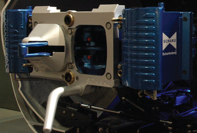

Figure 2: Photograph of a Scharfenberg coupler
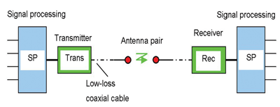

Figure 3: Working principle of the transmission system
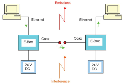

Figure 4: Test set-up
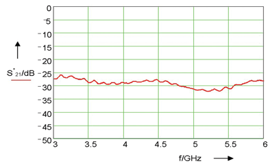

Figure 5: Transfer characteristic of a transmission system as a function of the frequency (measurement result)
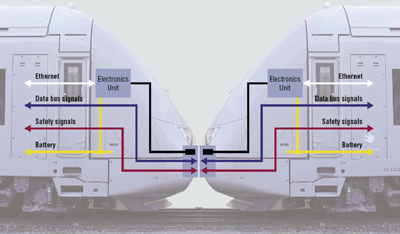

Figure 6: Transmission and distribution of on-board signals
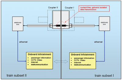

Figure 7: Integration of the microwave transmission into the on-board control systems
Some important requirements need to be considered:
• Cost savings through reduced number of electrical contacts
• High reliability in rough environments
• Electromagnetic compatibility (EMC, emissions and immunity)
• Future applications with high data transmission rates
Initial situation and state-of-the-art
Scharfenberg® railway couplers were established in 1903 and have proven their value as market-leading systems, with more than 300,000 couplers delivered. Figure 1 shows the functional principle of a modern coupler, whilst Figure 2 on page 72 shows a photograph.
Bridging data communication between railway cars is rather complex and expensive using current state-of-the-art technology. A large number of control signals for various train facilities need to be transmitted, requiring many electrical contacts. Depending on the design and the version of the train, the electrical heads can host more than 100 contacts. These contacts must have a very small transfer resistance, for example using a jack-pin combination.
Regarding the extended life-cycle, the large number of coupling procedures and possible adverse environmental conditions and heavy pollution, only high-quality materials and designs can be used. In addition, a large amount of extra data has to be transmitted, both for control tasks (e.g. via the wire-train bus) and passenger entertainment and information purposes (e.g. audio and video services). Current solutions include expensive coaxial cables and connectors.
Aspects of technical innovations and cost savings determine the enhancements, so that an advanced, contact-free design is the answer to many problems.
Comparison of technical solutions
In order to compare and evaluate suitable technical solutions, mechanical and electrical aspects as well as production requirements have to be considered. From the possible alternatives, these include:
• Infrared transmission
• Optical transmission
• Inductive coupling
• Short-range radio transmission with microwaves
The most promising version should be chosen.
The data rates that can be achieved using the inductive coupling method are too low regarding the increasing data transmission demands, although the other properties would be sufficient.
The use of a high-frequency application seems evident. The microwave range of frequencies, encompassing several GHz, looks very promising, with the additional advantage that new, specific components can be developed. In contrast to the microwave solution, the infrared and optical transmission solutions have disadvantages with respect to mechanical properties and are susceptible to pollution problems. Direct links between the railway cars using off-the-shelf wireless local area networks are not considered as they do not fulfil reliability, noise immunity and tap-proof requirements.
Important aspects
In order to determine a technical solution as well as to investigate and develop the desired transmission system, the following aspects have to be considered:
• Reducing the number of electric contacts in the coupler
• Developing a robust transmission system for the rough railway environment
• EMC conformity
• Simple mechanical design
• Coupling with on-board data bus systems
• Extension possibilities for increased data transmission rates and bandwidth requirements
Test set-up and typical measurements
The following measurements have to be carried out to determine essential parameters of the transmission system:
• Input impedance, reflection factor and directional characteristics of the developed microwave antennas
• Attenuation and received power of the transmission channel using an antenna pair,
• Cable attenuation for the selected frequency range
• Estimation of the required transmitted power
• Radiation characteristics (measured electrical field strength at a given distance)
• Noise immunity (external field generation)
Technical implementation
The implementation of the chosen solution includes the use of microwaves with a data transmission rate of 40 Mbit/s, higher rates are optional. The working principle of the transmission system is shown in Figure 3 on page 72. A key part of the system is the antenna pair, with specific properties matching the chosen frequency range and the dimensions of the coupler. The antennas are connected to transceivers via HF-adapters and low-loss coaxial cables. Transceivers are devices that can be used as transmitters and receivers (bi-directional transmission).
A number of investigations and tests were necessary in order to establish the system and check if all requirements were fulfilled. These tasks are listed below:
• Development of special control software to detect possible transmission failures
• Transmission tests with frequency-dependent characteristics on the one hand and reception of large amounts of data on the other hand
• EMC tests checking the immunity of the transmission channel by generating narrow- and broad-band signals
• Checking field-related radiations
The permitted electrical field-strength values for the GHz range have not been decided upon yet. However, a decision is expected for the future. In any case, mutual interferences between different transmission systems must be prevented, e.g. in case of two trains passing on parallel tracks.
Some frequency-ranges are open for public use, examples are shown in Table 1.
Of course, the named transmission channels can often be used for test purposes in order to allow an easy estimation concerning the performance of the system.
Restraints to be considered are given by the maximum allowed power of the transmitters. The result of a typical measurement with a Vector Network Analyser is shown in Figure 5 on page 74, where the transfer characteristic of the transmission system with a pair of specific microwave antennas has been plotted depending on a frequency between 3 and 6 GHz. The appropriate function is defined by S21*=10·log(Pr/Pt) dB=Pr*-Pt*.
Pt being the transmitter power and Pr being the received power. A typical value is given by a power of Pt*=15 dBm with relation to the reference of 1 mW, therefore Pt=31.6 mW.
Figure 5 on page 74 shows that the performance of the designed antennas is quasi-unrelated to the frequency, which is a very advantageous property. Assuming a value of e.g. 45 dB with reference to Figure 5 on page 74 and adding some dB to compensate for the unavoidable losses of the connected cables with required lengths, we end up with a receiver power level approximately Pr*≈-30 dBm, Pr≈1 μW. This shows that we have ample resources to create a reliable transmission system with sufficient signal-noise-ratio.
Application and conclusions
Different classes of signals have to be considered with regard to the integration of the microwave transmission system into the on-board control facilities:
• Signals for train protection and control
• Signals of the train bus
• Passenger information and entertainment
Stay Connected with Global Railway Review — Subscribe for Free!
Get exclusive access to the latest rail industry insights from Global Railway Review — all tailored to your interests.
✅ Expert-Led Webinars – Gain insights from global industry leaders
✅ Weekly News & Reports – Rail project updates, thought leadership, and exclusive interviews
✅ Partner Innovations – Discover cutting-edge rail technologies
✅ Print/Digital Magazine – Enjoy two in-depth issues per year, packed with expert content
Choose the updates that matter most to you. Sign up now to stay informed, inspired, and connected — all for free!
Thank you for being part of our community. Let’s keep shaping the future of rail together!


