Lateral separation cracks in concrete track slab
Posted: 31 May 2005 | | No comments yet
This article will cover the effects of lateral separation cracks in the concrete track slab on the durability of the RHEDA 2000® ballastless track system. The RHEDA 2000® ballastless track system consists of a jointless concrete track slab with bi-block lattice-truss concrete sleepers, on a hydraulically bonded layer (HBL), as shown in Figure 1. Unlike street and […]
This article will cover the effects of lateral separation cracks in the concrete track slab on the durability of the RHEDA 2000® ballastless track system.
The RHEDA 2000® ballastless track system consists of a jointless concrete track slab with bi-block lattice-truss concrete sleepers, on a hydraulically bonded layer (HBL), as shown in Figure 1.
Unlike street and road construction, the supporting concrete layer for the RHEDA 2000® is designed as ‘infinite’ in length. The basic concept prescribes a structural engineering Strength Class C30/37 or, for better assurance of frost resistance, Strength Class C35/45 may be applied. Inclusion of longitudinal reinforcement is not required to satisfy structural engineering requirements1. To accommodate restrained stresses, however, longitudinal reinforcement has been applied in the middle of the cross section, on the basis of experience gained from roadway construction: ø = 20mm, with 0.8 to 0.9% reinforcement percentage. This longitudinal reinforcement performs two functions:
- Limitation of the width of the unavoidable cracks, caused by the restrained stresses, to <0.5mm.
- Assurance of transfer of lateral forces at the edges of the cracks whereby the assumption of a continuous slab is justified.
The elaborations below will address the following questions:
- What relevance do lateral separation cracks have for the concrete track slab?
- Should lateral separation cracks in the track slab be sealed if exceeding a certain width?
Corrosion of reinforcement in cracks
Carbonation in the crack area
If CO2 from the air enters the concrete, the presence of sufficient moisture will cause production of carbonic acid, H2CO3. Carbonic acid will in turn react with the calcium hydroxide, Ca(OH)2, of the concrete pore water solution to produce calcium carbonate, CaCO3, accompanied by release of water. If calcium hydroxide from the solid Ca(OH)2 crystals of the hardened cement paste (matrix) are not subsequently dissolved, the pH of the pore water solution will fall below the passivation limit, which means that the reinforcement loses its corrosion immunity.
Before the carbonation front has reached the steel, however, it can be assumed – in cases of moderate crack widths – that a solution saturated with calcium hydroxide will develop on the steel at the base of the crack. This solution will protect the steel from depassivation. Systematic investigations have not yet been published on the particular crack width, beginning with which steel will no longer be covered with protective pore water.
In studies on carbonation in such cracks, Schießl2 has shown that assumption can be made of a final carbonation depth. This final carbonation depth will increase with the mathematical root of the crack width, and will decrease with the root of the so-called inhibition constant (the measure of the reduction of carbonation progress by means of hydroxide transport to the surface). Decreasing porosity of the concrete will be associated with reduction in this positive inhibitory effect, as less hydroxide will be transported to the surface.
Under assumption of the following; uninhibited diffusion of CO2 in air (i.e., no direct rainfall), an inhibition constant that can justifiably be assumed for concrete Class C30/37, and concrete cover of approximately 50mm over the reinforcement, the purely theoretic model supports the assumption that depassivation cannot be expected with cracks on the surface with widths of w <_ 0.35mm.
In work under the condition of rainfall and its effects – and from the assumable far safer standpoint of reduction of the CO2 diffusion coefficient in the crack of only approximately 30% – one can assume, for concrete cover of 50mm over the reinforcement, that corrosion resulting from carbonation cannot on the average be expected with cracks up to widths of w <_ 0.5mm. This reduction of 30% of the diffusion coefficient in the crack would approximately correspond to those conditions under which the share of days of a year in Germany in which rainfall with a level of at least 2.5mm occurs – i.e., the basis for assumption of days without carbonation activity for uncracked concrete directly subjected to the effects of rain3. To a slight extent, however, the considerable locally dependent fluctuations in carbonation depth (i.e., the carbonation peaks) can also lead to expectation of depassivation over the course of time for crack widths of w <_ 0.5mm and for larger cracks (which will take place only to a limited degree, owing to conformity with minimum reinforcement requirements). The crucial question consequently is: just when will this point in time be reached?
Schießl’s model2 shows that doubling of the amount of substance capable of carbonation (i.e. the hardened cement paste, or matrix) or doubling of porosity (more precisely the coefficient of diffusion) of the concrete will lead to doubling of the time until the final carbonation depth is reached.
The fact that the carbonation rate in the crack slows with increasing porosity of the concrete is due to the fact that under such conditions more CO2 enters through the crack into the flanks of the cracks, where it is subjected to chemical compound action – and after which it therefore is not available at greater depths for other chemical reactions. Increasing the crack width by a factor of two, results in increasing the carbonation rate in the crack by a factor of four. The essential finding here is that increasing the concrete coverage by a factor of two, results in increasing the time by a factor of 16 until the final carbonation depth is achieved.
Experiments under dry indoor conditions have verified the correctness of the relationships as described above2. It was not possible, for purposes of model calibration, to apply analyses of components directly subjected to rainfall, owing to the very slight progress of carbonation in the cracks of concrete beams exposed to the elements over a period of ten years. These circumstances are furthermore compounded by the following phenomena: in addition to inhibition of CO2 diffusion by water filling the cracks – and/or by the increasing re-alkalisation of the crack flanks owing to the cycles of wetting and drying – the aspect of self-healing of cracks also contributes to the process of carbonation. The probability of crack healing by the sintering-out process occurring in the concrete increases with a reduction in crack width. Self-healing processes that occur in concrete cracks result from various causes: e.g. swelling of the hardened cement paste in the flank of the crack (which is a reversible process), progressive hydration activated by additional entry of water, and – primarily – by formation of calcium carbonate due to carbonation of hydroxide which had been transported out of the concrete core to the flank of the crack. It may be assumed that frequent, direct rainfall onto the RHEDA 2000® concrete track slab is associated with a greater possibility of complete healing of cracks with relatively small widths.
Qualitatively the following conclusions can be kept in memory:
- The effects of frequent wet-dry cycles on the concrete track-supporting layer will most likely result in a significant inhibition of carbonation.
- The concrete cover of the reinforcement is by far the most important influencing variable for prevention of corrosion resulting from carbonation of the concrete in cracks.
- Despite the fundamentally great spread in carbonation depths observed at the edges of the cracks, and under the observed conditions of relatively thick concrete coverage of the lattice-truss elements of >_ 50mm (the longitudinal reinforcement has considerable greater coverage, see Figure 1), it can be assumed that the probability of reinforcement corrosion is only very slight over the planned service life of 60 years for this ballastless track system.
Depassivation in crack area as a result of chloride exposure
Exposure to water containing chloride is usually negligible in the case of the RHEDA 2000® concrete track slab, for the following two reasons:
- No de-icing salts are used on the track sections involved.
- The distance to other possible sources of chloride (e.g. highways, roads, or coastal areas) is normally too great to produce any noteworthy exposure to chloride4.
In contrast, track sections directly above bodies of seawater can lead to considerably elevated chloride exposure, even at elevations of h > 25m. A model comparable to that used for carbonation in cracks is not currently available for exposure to chloride. Basically, however, it can be assumed that extensive exposure to water containing chloride would result in extremely rapid entry of chloride into the concrete cracks. Extensive studies, however, have confirmed that, in case of moderate crack widths (i.e. up to approximately 0.5mm), the subsequent corrosion process itself does not depend on crack width; rather, the thickness and the quality of the concrete coverage of the reinforcement are primarily of decisive importance5, 6. As a result, for track structures with concrete cover over reinforcement of more than 40mm, and with the water-cement ratios w/c <_ 0.5 used for the track slab of the system RHEDA 2000® only slight surface rust can be expected; even after relatively long exposure times and under highly unfavourable environmental conditions.
The corrosion phase
The corrosion process can be broken down into two sub-reactions, which take place at different places on the reinforcement. The anodic sub-reaction involves the dissolution of iron with release of electrons: i.e. Fe → Fe+2 + 2e-; oxidation. At the cathode, the reduction of the electrons released in the anodic sub-process normally takes place in the presence of water and oxygen: H2O + 0.5 · O2 + 2e- → 2(OH)-. Iron ions and hydroxides form iron (II) hydroxide, Fe(OH)2, or iron (III) hydroxide, Fe(OH)3. According to the presence of moisture in the concrete, these compounds are transformed into various modifications of rust products: e.g. FeOOH, Fe2O3, or Fe3O4.
The anode and the cathode together act as a battery between the poles of which an electric voltage is present (see Figure 3). This voltage causes electrons (e-) within the steel to migrate to the cathode. In the concrete, hydroxide ions (OH-) migrate to the anode, and iron ions (Fe+2, Fe+3) move to the cathode. A simple electric equivalent circuit for this corrosion process can be derived, which includes the following: voltage between the anode and cathode as driving force, dissolution of iron (anodic partial resistance), conduction of ions in the concrete (electrolyte resistance), and diffusion of oxygen and reaction with water and electrons to form hydroxide (cathodic partial resistance).
The removal of mass from the steel is directly proportional to the prevailing electric current: i.e. it is therefore directly proportional to the voltage V between anode and cathode, and inversely proportional to the sum of the partial electric resistance values. Although this model represents an extreme simplification – especially with respect to the geometric configuration of the anodes and cathodes – it does in fact fully suffice to clarify the main influences on the corrosion process.
In cracked concrete it can be assumed that the steel surface, with removal by corrosion (the anode), is always present in the area of the cracks; as it is here that depassivation resulting from the crack will most readily take place. Distinction is necessary between the following two fundamental cases:
- Microelement corrosion: Here, the reinforcement corrodes in the manner of unprotected steel, whereby surface components that act as cathodes and anodes are directly adjacent to each other. Basically, in cases of microelement corrosion as a result of carbonation of the concrete in the area of the crack, the geometry of the crack (i.e. its width and length) has no influence on the corrosion rate, and it may be assumed that corrosion depth at the reinforcement will be shallow.
- Macroelement corrosion: In these cases, the reinforcement in the area of the crack acts as an anode. The longitudinal reinforcement of the concrete track supporting layer – and the lattice-truss reinforcement (electrically connected to the longitudinal reinforcement) of the sleepers in uncracked concrete – function as a large-area cathode. Now, as before, oxygen access to the cathodes in the concrete remains possible. Under these conditions, steel-removal takes place at a rate faster than for microelement corrosion.
The less the exposure to oxygen in uncracked concrete, and/or the less the electrical conductivity of the concrete, the less the progress of the corrosion as a result of macroelement formation. In the case of a controlled cathodic partial reaction as a result of oxygen diffusion, purely theoretical considerations would lead to the assumption under these circumstances that even an increase in the rate of steel removal would take place. This would theoretically result from the fact that the ratio of the cathodic area to the anodic area would increase, and that the effects of cathodic control would progressively decline. However, the branching of cracks in the vicinity of the reinforcement presumably reduces the noteworthy occurrence of this phenomenon. Especially in conjunction with chloride-induced corrosion in a crack, considerable significance must ultimately be attributed also to the aspect of high anodic polarisation resistance. This resistance explains the absence of pitting in the crack area in cases of sufficiently thick and impermeable concrete cover over the reinforcement – despite depassivation of the steel surface. To be sure, if the crack width at the surface of the steel is sufficiently small, if the quality of the concrete cover is sufficient to withstand the bursting pressure of incipient corrosion, and if the concrete cover is impermeable enough to sufficiently restrict the outgoing transport of iron ions, then the enrichment of iron ions will lead to the effect of concentration polarisation and, in turn, to an increase in anodic partial resistance (see Figure 3).
The above evidence supports the following conclusion: even in the case of macroelement corrosion, cracks with widths within a moderate range play no significant role in influencing the rate of corrosion. The thickness and the impermeability of the concrete cover over the reinforcement are decisive for determining the progress of corrosion.
Conclusions on the effects of cracks on reinforcement corrosion
The width of cracks in concrete essentially depends on the tensile strength of the concrete, the bond between concrete and reinforcement, concrete cover over the reinforcement, the configuration of the reinforcing bars, and the thickness and the form of the concrete components. In this context, there is a great spread in the values encountered for concrete tensile strength, the characteristics of the bond between steel and concrete, and the corrosion depth at the reinforcement as a result of corrosion in the cracks. The width of the lateral cracks is of secondary importance with respect to corrosion rate, insofar as the yield strength of the steel is not exceeded: i.e. as long as excessively wide cracks (>> 0.5mm) do not occur. The decisive factor for corrosion protection, accordingly, is not the crack width, but primarily the thickness and the impermeability of the concrete cover over the reinforcement. This conclusion leads, in turn, to the following consequence: the application of complicated formulas for restriction of crack width only mimic prediction exactness that could not in any case be observed – and would, more importantly, only distract consideration from the actually critical parameters as described above.
In accordance with published recommendations6, simple structural-engineering regulations in the form of limits on reinforcement-bar diameters and bar intervals were for the first time introduced in the DIN 1045 version published in 1988, in order to restrict the width of cracks7. These regulations were intended to prevent the occurrence of excessively wide individual cracks8. The stipulations were based on a design value for crack width of w = 0.25mm for construction components installed outdoors that are subject to frequently changing conditions of moisture penetration, with or without exposure to substances that especially promote corrosion (primarily chloride, from the use of thawing salt, or from seawater exposure). This design value has been selected for application owing to the pronounced spread encountered in values for crack width, in the sense of a quantile value, and will reliably enable prevention of cracks with w >> 0.5mm. Owing to the large spreads encountered in crack widths, application of the above stated design value implies the following: that cracks in actual practice can, in fact, also become larger and, more importantly, that exceeding these limit values will not automatically signify insufficient durability. The currently valid standard DIN 1045-1, dated 20019, now merely stipulates a design value (not maximum value) of w = 0.3mm, for purposes of preventing chloride-induced or carbonation-induced corrosion.
For application of the RHEDA 2000® system, the thickness of the concrete cover over the longitudinal reinforcement reliably supports the assumption that corrosion will not occur there during the life cycle of the system (see Figure 1). Consequently, the only remaining case requiring consideration is the possibility of corrosion of the lattice-truss reinforcement for the RHEDA 2000® bi-block sleeper (see Figure 4).
The primary purpose of the lattice truss before installation is to ensure maintenance of the proper gauge. During installation, it can (if required) be used as an assembly aid. After installation, it assures sufficiently secure integration of the sleeper into the concrete track slab.
In consideration of the course of the crack, and at the same time in combination with the position and depth of the reinforcement, it becomes clear that – as worst case – the possibility exists of spot-type corrosion of the uppermost strut of the lattice truss. As a result, it is not probable – with the concrete cover and the concrete quality as applied in such cases – that spalling of the concrete could take place as a result of volume increase caused by the products of corrosion. As only a small fraction of the lattice truss reinforcement can demonstrate corrosion and, if so, only on a locally limited basis, the reinforcement remains properly integrated in the concrete layer, and the serviceability of the system is guaranteed during the intended life cycle.
Relevance of cracks with respect to frost damage
In the flanks of the concrete cracks, it can be basically expected that the water saturation of the concrete will take place more extensively and over longer periods of time than is the case for the uncracked concrete surface. In cases of concrete that is fundamentally safe from frost in uncracked areas, deeply extending structural damage to the concrete is, likewise, not probable here. These relationships are also reflected in the currently valid standards: none of them specify limitation of crack widths for prevention of frost damage.
In conjunction with cracks along the sleepers, the question arises at any rate on whether frost exposure would impair the integration of the sleeper: especially on the bottom sleeper side. Concrete core samples10 have proved that – if the concrete consistency is fully satisfactory (i.e. if there is no noteworthy bleeding of the concrete), and if the concrete has been properly compacted – almost complete underfilling of the concrete sleepers is achieved. At this concrete level, therefore, the danger can be excluded that seepage and as a result disintegration of the concrete at the bottom side of the sleepers (i.e., the area of traffic load application) will occur due to frost action.
Relevance of cracks on erosion of the HBL
From the context of construction of concrete roads and streets, the mechanism of so-called ‘slab pumping’ is known, causing erosion of the hydraulically bonded layer (HBL) in the domain of slab joints. The load-distribution action of the elastic rail suspension in the RHEDA 2000® leads to loads applied at the edges of the concrete cracks along the sleepers, which are slightly less than those that occur from heavy vehicle traffic at the edges of concrete street and road slabs. The resulting deformation of the HBL and, in turn, the movement taking place in the edges of the cracks, may consequently be considered to be comparable. The advantage of the RHEDA 2000® over a roadway concrete slab (with dowels installed by vibration compaction of the fresh concrete) are twofold. Firstly, the longer dowel length of the longitudinal reinforcement (which acts as anchors) and secondly, significantly greater positioning precision. Dowel lengths of < 100mm and installation positions excessively deep with reference to the centre of the cross sections can lead to overloading of the concrete in the vicinity of the dowels and, in turn, to increased deformation11. In addition, cavities at the reinforcement are practically impossible with RHEDA 2000®. Where they do occur in other systems, they result in cracks, spalling, and the consequent insufficient dowel action that gives rise to relative movement of the edges of cracks, as is the case in dowels installed by vibratory compaction. So-called ‘slab pumping’ can accordingly be excluded for the RHEDA 2000® track system. Consequently, it may be concluded that no efforts are necessary to restrict the width of cracks in the concrete track slab. Rather, emphasis must be placed on proper composition, compaction, and lateral sealing of the hydraulically bonded layer (HBL), in order to prevent washing-out of fines by runoff water to an extent which could lead to significant damage by structural loosening.
Conclusions on the relevance of cracks and the necessity of restricting crack width
In this context, the restriction of crack widths to w <_ 0.5mm is considered to be advisable: conformity to which would include the associated – and therefore by all means likewise to be accepted – probability of exceeding this width. This signifies, in other words, that individual cracks with w > 0.5mm do not require grouting as long as the average crack width (measured in winter) yields the condition of approximately w <_ 0.3 mm, as stipulated by DIN 1045-19. The above given criteria corresponds to the safety concept proposed by Schieß8, who applies a scattering (safety) factor of k = 1.7, corresponding to a 95% safety level.
The following caveat is essential: the mere observance of this crack criterion by no means provides assurance that a durable track system will result, since concentration on crack width diverts attention from conformity to far more important influencing variables. These more important factors are composition, placing, and curing of the concrete of the track-supporting layer and the HBL. Under the condition of proper handling, the concept of the RHEDA 2000® system automatically assures conformity with respect to the main influencing variable: i.e. the position of the reinforcement.
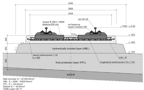

Figure 1: System cross-section of the RHEDA 2000
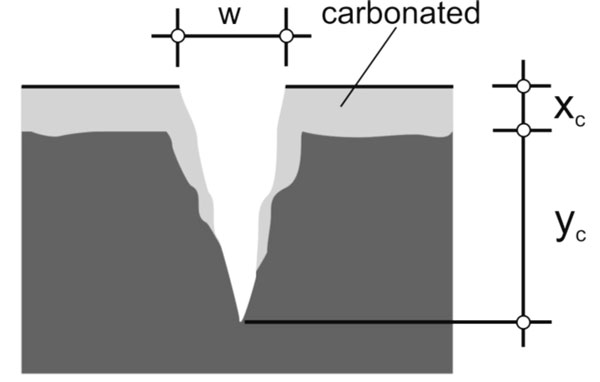

Figure 2: Schematic on carbonation in the concrete
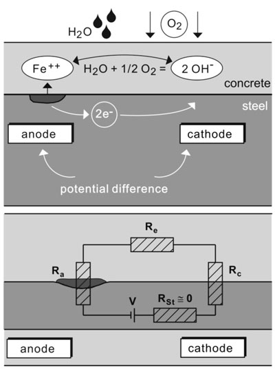

Figure 3: Schematic model for the corrosion of steel in concrete


Figure 4: Schematic representation of a crack along a RHEDA 2000 bi-block sleeper
References
- Eisenmann, J.; Leykauf, G.: Feste Fahrbahn für Schienenbahnen, Betonkalender, Band 2, Ernst & Sohn Verlag, Berlin, 2000, pp. 291-326
- Schießl, P.: Zur Frage der zulässigen Rissweite und der erforderlichen Betondeckung im Stahlbetonbau unter besonderer Berücksichtigung der Karbonatisierung des Betons, DAfStb Heft 255, Berlin, 1976
- DuraCrete: Brite EuRam III Project BE95-1347, Report R4-5, Modelling of Degradation, 1998
- Lay, S.: Models for the prediction of the residual service life, Report D3.2, EU-Project LIFECON, G1RD-CT-2000-00378, Munich, 2003
- Gehlen, C.; Pabsch, G.: Influence of cracks upon corrosion, Report, EU-Project DARTS, GRD1-25633, Munich, 2004
- Schießl, P.: Einfluss von Rissen auf die Dauerhaftigkeit von Stahlbeton- und Spannbetonbauteilen, DAfStb Heft 370, Berlin, 1986
- DIN 1045-88: Beton und Stahlbeton – Bemessung und Ausführung, Berlin, 1988
- Schießl, P.: Grundlagen der Neuregelung zur Beschränkung der Rissweite, DAfStb Heft 400, Berlin, 1989, pp. 159-175
- DIN 1045-1: Concrete, reinforced and pre-stressed concrete structures, Part 1: Design, Berlin, 2001
- Koenders, E.A.B.: Settlement tests, Report No. 25.5-03-21, Technische Universiteit Delft, Faculteit Civiele Techniek & Geowetenschappen, 2003
- Freudenstein, S.: Untersuchungen über den Einfluss reduzierter Dübeleinbindelängen auf die Wirksamkeit der Fugenkonstruktion bei Betonstraßen, doctoral thesis, Lehrstuhl und Prüfamt für Bau von Landverkehrswegen der TU-München, 2001
OUT NOW: The Definitive Guide to Rail’s Digital Future
The rail industry is undergoing a digital revolution, and you need to be ready. We have released our latest market report, “Track Insight: Digitalisation.”
This is not just another report; it’s your comprehensive guide to understanding and leveraging the profound technological shifts reshaping our industry. We move beyond the buzzwords to show you the tangible realities of AI, IoT, and advanced data analytics in rail.
Discover how to:
- Optimise operations and maintenance with real-time insights.
- Enhance passenger services through seamless, high-speed connectivity.
- Leverage technologies like LEO satellites to improve safety and efficiency.
Featuring expert analysis from leaders at Nomad Digital, Lucchini RS, Bentley Systems and more, this is a must-read for any rail professional.


