High-speed trains: from power car to distributed traction
Posted: 6 June 2007 | | 1 comment
Over recent years, the level of satisfaction among train passengers has continually increased thanks to new attractions offered by high speed trains. Attractive travel times and additional services in the trains are designed to increase the competitiveness of the rail. Building on experience with the trains of the ICE series that were developed by a consortium, Siemens has been able to establish the Velaro platform at a worldwide level with trains for Spain, China and Russia. In addition to the high speed trains for upgraded lines, it can make perfect sense to operate passenger coaches.
Over recent years, the level of satisfaction among train passengers has continually increased thanks to new attractions offered by high speed trains. Attractive travel times and additional services in the trains are designed to increase the competitiveness of the rail. Building on experience with the trains of the ICE series that were developed by a consortium, Siemens has been able to establish the Velaro platform at a worldwide level with trains for Spain, China and Russia. In addition to the high speed trains for upgraded lines, it can make perfect sense to operate passenger coaches.
Over recent years, the level of satisfaction among train passengers has continually increased thanks to new attractions offered by high speed trains. Attractive travel times and additional services in the trains are designed to increase the competitiveness of the rail. Building on experience with the trains of the ICE series that were developed by a consortium, Siemens has been able to establish the Velaro platform at a worldwide level with trains for Spain, China and Russia. In addition to the high speed trains for upgraded lines, it can make perfect sense to operate passenger coaches.
With the increasing requirements for mobility, the significance of rail traffic has increased in the past years. Congestion on the roads, combined with growing environmental awareness and emphasis on safety, is causing more and more people to use the rail alternative. In order to further increase the competitiveness of the railway, short travel times must be supplemented by an attractive interior design of the trains.
With its portfolio of high speed trains of the Velaro platform and the passenger coaches of the Viaggio family, Siemens offers the perfect train concept for the different requirements of the railway operators.
In May 2007, the AVE® S 103 high speed train (Velaro E), a comfortable multiple unit train with distributed traction, will officially enter passenger service in Spain. Running at a top speed of 350km/h, the train will take less than 2.5 hours to travel on the Madrid – Barcelona line, offering customers an attractive alternative to one of the world’s busiest flight routes.
The development of the Velaro high speed platform is based on the experiences and findings that were gained from the operation of the ICE® fleet of the rail operator Deutsche Bahn in Germany.
An economical complement for “real” high speed traffic is provided by modern passenger coaches for Intercity traffic with speeds of between 230 and 250 km/h.
The early days of high speed transportation
The era of high speed on the rail began in Japan in 1964 with the Shinkansen, which used distributed traction to achieve top speeds of 210 km/h1. Based on the great success in Japan, corresponding projects were also reviewed in Europe. While the concept of the permanently coupled unit with power cars was tested for the TGV (Train à Grande Vitesse), Germany also decided in favor of developing the rail network and the rolling stock for higher speeds to improve the competitiveness of the railway. In a cooperation between government and industry, corresponding high performance trains for top speeds of over 200km/h were to be developed2. Germany also decided to test the concept of permanently coupled multiple unit trains in a first step.
The Intercity Experimental test and demonstration train (later known as ICE V) lays the foundation of high speed in Germany
The concept was validated for its feasibility by means of the ICE V demonstration vehicle starting in 1985. In addition to examining the components at speeds up to 350km/h and the power ratings, the goal was to reach the highest possible speed in the rail network of Deutsche Bahn.
The ICE V was composed of two identical power cars, a test car and two demonstration cars. The power cars were each equipped with four three-phase asynchronous motors that have a total power rating of 3640 kW. The power supply was ensured by a pantograph that was installed on each power car at the semi-permanently coupled end. In order to avoid contact problems, only one pantograph was to be used at any time, which was why a 15 kV high voltage line was installed on the train roof.
In this experimental vehicle, the eddy current retarder was already tested that later reached production maturity in the ICE 3.
In 1988, the ICE V with two intermediate cars established the then speed record on the rail of 406.9 km/h3.
First- and second-generation ICE with power car technology
Based on the experience gained in the test runs of the ICE V, the Intercity Express trains of the first generation were designed by an industry consortium. In 1991, passenger service started on the Hamburg – Munich line. The trains consisted of two power cars and up to 14 intermediate cars, with the maximum train length of 400 m being limited by the length of the platforms. The cars are permanently coupled, so that the train formation can only be separated in the depot. At this time, the train also set new standards with respect to the interior design of the passenger compartments: spacious entrance vestibules and newly designed wide and comfortable seats ensured a pleasant ride. A spacious restaurant car as well as the comfortable first class offering with its wide seat spacing and various communication options completed the program.
Currently, the vehicles of the ICE 1 fleet – after 14 years of reliable passenger service with an annual mileage of up to 500,000 km per train – are being subjected to an overhaul of their technical equipment and interior furnishings4.
In 1996, passenger service using second-generation ICE trains commenced on the Frankfurt (Main) – Hanover – Bremen line. With respect to appearance and electrical equipment, the ICE 2 continued the development line of the ICE series. In order to permit a more flexible deployment of the high speed trains, a multiple-section concept was implemented for the ICE 2. Two half-trains, each of them 205m long, can be coupled to run as an extended trainset by means of couplers type Scharfenberg that are installed behind a two-part pneumatic front coupler door. A half-train consists of a power car, six intermediate cars and a purpose-designed control car. In order to retain the bidirectional capability of the ICE 2 trains, it was required to ensure sufficient side wind stability of the light control car.
Another achievement that improved the comfort for the passenger in the ICE 2 by providing a significantly higher ride quality was the development of the type SGP 400 bogie with air suspension.
While the ICE 1 still had multiple passenger compartments, the ICE 2 uses an open-plan design. With electronic displays in every vestibule, info display on the end walls of the open-plan compartments, an exterior train-route display, an electronic seat reservation system and loudspeakers in all passenger areas, the passenger information system provides perfect information to the passengers. For entertainment, each seat is equipped with an adjustable 8-channel audio module, and the first class seats with folding tables feature an additional video station.
Multiple unit trains with distributed traction as an optimum response to the requirements of Deutsche Bahn
Work on the third train generation of the ICE was well underway already during the introduction of the ICE 2 for passenger service. In this process the basic traction concept with the two power cars was reviewed. The range of requirements included the following specifications from the then emerging “Technical Specifications for Interoperability” for European high speed traffic5:
- Maximum train length 400m
- European clearance envelope according to UIC 505 with consideration of special agreements between Deutsche Bahn AG and the French state railway SNCF
- Maximum static axle load of 17 tons
- Platform heights 760mm and 550mm
- Maximum line speed at least 300km/h
- Operation with all four European contact line voltages (AC 15 kV / 16.7Hz, AC 25 kV / 50Hz, DC 1.5 kV and DC 3 kV)
- Equipment with the train protection and communication systems of the served lines and the future European system, respectively
The customer also requested maximum speeds of 300km/h on the new high speed line Cologne – Frankfurt with gradients of up to 40‰ and also a high acceleration force so that the train could also be optimally operated on the existing lines. In addition, it was required to reduce the costs per seat, despite the higher performance requirements, by 25% compared to the ICE 1. The existing power car concept was no longer able to provide the limitation of axle loads to a maximum of 17 tons in conjunction with the requested maximum speeds under all four European contact wire voltages on lines with higher up-gradients as well as the required increase of seating capacity while ensuring the same level of comfort. A multiple unit train with distributed traction and consequently reduced axle load, improved traction performance and higher seating capacity with the same train length would be significantly more suitable to meet these requirements.
Two experimental vehicles – ICE D and ICE S – were built in order to qualify the multiple unit concept that was an innovation in the high speed sector in Europe; it used traction components that were evenly distributed in the underfloor area. The ICE D was designed to demonstrate the suitability of the distributed traction system in passenger service (the “D” stands for the German term “Dauerbetrieb”, meaning “continuous service”). The ICE S was used to verify the suitability for high speeds (“S” for “speed”).
With the experimental trains ICE S and ICE D, the testing and certification of the components for future high speed train generations for reliable operation was more important than more high-prestige record runs at top speeds6.
With the ICE D, the reliability of the traction technology of the powered intermediate car was demonstrated in continuous service.
To ensure the suitability and reliability of the new traction components7 for continuous service in high speed traffic, the ICE D was operated for about two years in roundtrip mode between Hamburg and Munich with a daily running performance of about 2,000km.
The ICE D consisted of the first-generation multiple unit train 13, two power cars of the ICE 2 as well as an intermediate car that was added directly after a power car. This was equipped with powered bogies of the future ICE 3, the traction motors of which were powered from one of the two traction converters of the power car.
The ICE S tests components for distributed traction.
At the same time, however, it was also desired to ensure the functionality of other components. For this reason, a second experimental train – the ICE S – was used to ensure the following aspects:
- Optimization of the pantographs
- Validation of the linear eddy current retarder
- Development of new HVAC technology
- Improvement of the sound insulation
- Testing of the powered intermediate cars
- Demonstration of the suitability of the traction system with spiral- toothed coupling
- Tests of the track superstructure and the overhead contact line, for which the ICE S is used until today, e.g. for test runs on the new Nuremberg – Munich line
Design of the ICE S
The 5-car ICE S was comprised of two power cars (ICE S-TK), two powered intermediate cars and a test car with transformer. The two power cars were acquired by the research and test center of Deutsche Bahn AG in Munich as experimental and test vehicles, e.g. for line tests. They used the same design as the power cars of the second series but had a gear ratio that was adjusted for a maximum speed of 400 km/h. The three intermediate cars of the ICE S offered the same functionality as a 4-car unit of the future ICE 3 and had a tractive effort of 4MW. In the ICE S, the three intermediate cars were also required to accommodate the battery charger and battery for the operation of the onboard power system, which were to be installed in the fourth intermediate car in the production train.
Traction concept
The ICE S had a total traction power of 14 MW, which roughly corresponds to the power of three ICE 2 power cars and gave it an extremely fast acceleration capability.
As shown in Figure 2, the ICE S has a total of five pantographs: One pantograph on each of the power cars, a newly developed high speed pantograph on the test car, 25kV pantographs with narrow pan for the French and Belgian network and a DC pantograph for 1.5kV and 3kV operation in the Netherlands and in Belgium. The last two units were not electronically connected but were rather used for aerodynamic and contact force measurements.
As with the ICE V concept, power was to be provided via a single pantograph. For this reason, the three pantographs for the AC power systems were interconnected with a 15kV high voltage roof cable.
The main transformer in the test car supplied the converters, each of which consisted of 4-quadrant choppers8 on the line side, which fed power to the PWM inverter via a DC link. In this manner, four asynchronous traction motors with 500kW of power each were supplied with power in the adjacent intermediate cars.
Innovative powered and non-power bogies were used to ensure the top speed and maximum travel comfort. The powered bogies of the intermediate cars were equipped with two different traction systems9:
The intermediate car 1 tested an axle-mounted traction system with spiral-toothed coupling that was oriented at the traction concept of the Shinkansen generations and used for the first time on a European high speed train.
In order to have an alternative in case that the tests with the axle-mounted drive prove unsuccessful, the intermediate car 2 was equipped with an already proven classic fully suspended traction system that transmitted the tractive effort via a hollow cardan shaft. However, the results of the design with the spiral-toothed coupling were fully convincing.
The test car was equipped with a non-powered bogie with eddy current retarder. To comply with the requested braking distances of the ICE 3 for long down-gradients at maximum speeds of 330 km/h, three different braking systems were installed and tested on the ICE S. The linear eddy current retarder in the test car supported the regenerative brake that was already used in the ICE 1 and ICE 2. To ensure the breaking distances in case of failure of these systems, a pneumatic disk brake was integrated as the third braking system. For the first time, a gradual application of the braking effort was used. In order to reduce the wear of the brake linings at high speeds, braking occurred with half the effort. This system is also used on the ICE 3.
Until today, the ICE S is used on national and international routes with a single intermediate car for measurements that was modified in 2006. It was e.g. used for test runs on the new high speed line Munich – Nuremberg in Germany. In December 2006, it established the Swiss speed record on the rail.
The ICE 3 – a multiple unit train for Europe
The third-generation ICE was designed and implemented as a multiple unit train for Europe on the basis of experiences with the ICE D and ICE S. The ICE 3, which was designed as a European multi-system train from the beginning, can operate in four European power systems. The ICE 3 is the first European train that permits a smooth in-service transition between different control systems, enabling time-saving cross-border traffic between the six countries Germany, Austria, Belgium, France, the Netherlands and Switzerland10. In keeping with the international tradition, the premiere of the first third-generation trains took place in the special timetable for the Expo 2000, so that visitors from all over the world were able to reach the world exhibition in Hanover both comfortably and reliably.
This train also incorporates the proven multi-section concept of the ICE 2 – two half-trains of the ICE 3, consisting of eight cars, can be coupled to form a 400m long train if required. Four of the eight cars are powered.
Traction concept
The traction concept corresponds to the proven concept of the ICE S with a single-speed axle-mounted gearbox with spiral-toothed coupling and three-phase asynchronous motors that deliver 500kW of traction power.
The two transformer cars are interconnected by a high-voltage roof cable, so that the multiple unit train can operate in AC power systems with a single raised pantograph. With the multi-system train (MS), the additional pantographs for operation in the AC 25kV power system that are directly connected to the high-voltage cable are installed on the two intermediate cars. Since the pantographs for operation in the DC 1.5kV and 3kV systems on the two converter cars are not electrically interconnected, the power in DC systems is supplied via two raised pantographs. Single- and multi-system transformers are of largely identical design. The switchover of the secondary connections for the transition from AC 15kV to AC 25kV is made in a separate disconnector rack.
The converters in the single-system train (ES) are of the same design as the equipment of the ICE S. For runs in the 25kV system at 50Hz, a low-inductivity harmonic filtering inductor is used, and the clock rate of the line-side 4-quadrant chopper is adjusted. For operation in DC power systems, the two traction converters in the converter car and in the end car are interconnected via chopper reactors and system changeover switches and operated directly on the line voltage as a DC chopper via the line filters that are matched to the requirements of the DC power supply systems.
The 4-quadrant chopper and the PWM converter consist of water-cooled phase modules of identical design, each of which is comprised of two GTO thyristors and two free-wheeling push- pull diodes, the snubber circuit, and the drive unit.
Comfortable interior furnishing and numerous supplemental offerings increase the attractiveness of the ICE 3
The ICE 3 also combines its high speed technology with design and comfort. Due to the multiple unit concept, it offers more space for passengers. Depending on the exact choice of the interior furnishings, a half train provides 430 – 460 seats (compared to an average of about 391 seats in the ICE 2). Since all traction components are installed in the underfloor area, a continuous passenger area was created. The possibility to enjoy the panoramic view in the lounge to the track ahead – separated from the driver only by a glass partition wall – is certainly a highlight for every passenger.
Among other features, the passenger information system comprises a service and paging system for 1st class passengers, selected areas of the train with improved conditions for mobile calls, six stereo broadcast programs for all passengers, loudspeakers and displays (see figure 7) as already installed in the ICE 2.
Onboard Internet permits especially business travelers to make optimal use of the travel time
Deutsche Bahn AG introduced the possibility to access the company network and process emails on-line via the Internet in selected stations and train connections by using the wireless local radio network WLAN (Wireless Local Area Network). In the pilot phase, Deutsche Bahn and T-Mobile Deutschland, with the cooperation of T-Systems, equipped selected stations and line sections as well as several ICE trains with the advanced radio technology. T-Systems developed a system architecture that permits the stable, high-performance connection of high speed trains to the World Wide Web. This service is available in the seven ICE trains that are equipped accordingly on the pilot line between Cologne and Dortmund as well as on the Frankfurt – Hanover – Hamburg line. In other parts of the line, the local information offering is available on the train, which is updated in selected stations. Deutsche Bahn AG plans to retrofit a total of more than 50 ICE trains with this technology.
The Velaro platform – multiple unit technology worldwide
The Velaro platform is the logical continuation of the multiple unit concept of the ICE. The design is oriented on the ICE 3 but was customized to meet the requirements of the Spanish railway operator Renfe. The multi-section concept is reused here because it makes the trains flexible: A double train can be subdivided into two trains for different final destinations if required.
Adaptations in the traction concepts of the Velaro E vs. the ICE 3
The power of the main transformers was increased by 10% over the ICE3 fleet, in order to enable the higher traction power. An important step from an ecological point of view is the use of the ester coolant instead of mineral oil11 for the main transformer.
The Velaro E uses an advanced pantograph for the requirements of speeds over 300km/h.
A change from the existing converters of this class is the installation of a step-down chopper and of an auxiliary traction auxiliary converter in IGBT technology on the traction DC link that feeds power to the auxiliary traction equipment even in case of a line failure.
The gearbox is based on the proven concept of the axle-mounted traction system with spiral-toothed coupling but was redesigned with a focus on optimized noise performance according to the new standard EN 13104. This ensures a noise level that is up to 10% lower than that of the ICE 3 gearboxes.
For the Velaro E, the regenerative braking system was supplemented with a rheostatic brake that can absorb the electrical braking energy of the traction motors if it cannot be fed back into the line system.
Based on the operating experience in the ICE, the traction system of the Velaro E is designed so that the failure of one traction unit will not affect the other traction units and the train reaches its destination typically without loss of travel time at 75% of the maximum traction effort. The low-maintenance three-phase asynchronous motors have demonstrated their reliability and ensure maximum availability.
In July 2006 maximum speeds over 400km/h were reached with a Velaro E train of the original not adapted serial production.
Three-class system
To provide an attractive offer that compares with airplanes, the Spanish National Railway operator Renfe offers its passengers a three-class system, setting new standards. A seating capacity of 404 – up to 56 seats less than on the ICE 3 – ensures ample legroom for the passengers. The Premium class is located in the front section of the train and offers a meeting and VIP room directly behind the driver’s cab as an attractive environment for meetings.
A corresponding first-class catering service with in-seat meals completes the offering in this class. This exquisite class is directly followed by the Preferente class, which roughly corresponds to first class on the ICE 3 trains. It has an in-seat service for small meals. In these two classes, almost all seats can be rotated so that passengers are looking in the direction of travel. The transition to the Turista area, which is furnished in a similar way as a second-class vehicle of the ICE 3, is formed by a Cafeteria car. The Turista also has its own lounge, which is located directly behind the driver’s cab.
The passenger information system was also built on existing experience and the latest information technologies. In all sections, information and entertainment content are provided via ceiling monitors and individual audio programs. The public address system permits selective announcements for individual cars or car classes.
By implementing the described three class system which is aimed to meet the individual convenience of different customer groups with a comfortable interior decoration combined with a constant high traveling speed, Renfe establishes with the AVE S103 a train which can stand any competition with the high frequented flight connection between Madrid – Barcelona.
Summary of 10 years of operating experience with multiple units and outlook
The results of the test that were performed on the ICE S and ICE D ten years ago form the basis for the development of the successful high speed concept. The Velaro platform is based on the revolutionary step from the multiple unit train to the distributed traction system, which could only be achieved with the experimental vehicles ICE S and ICE D. The test runs with these trains demonstrated the suitability of the axle-mounted traction system with spiral-toothed coupling, an innovation in Europe at that time, and of the distributed traction system in an impressive manner for the first time.
The ICE 3 fleet has proven its value in daily passenger service since 2000. The Velaro E is ready for passenger service and has already successfully navigated 50,000 km in test runs. The high speed trains of the ICE family and the Velaro platform have covered distances over 100,000,000. The advantages of the multiple unit concept, including:
- Larger passenger compartment with the same train length
- Reduced adhesion requirements
- Ability to run on sections with up-/down-gradients up to 40 ‰, providing more flexibility for the infrastructure operator with cost-optimized route design
- Even weight distribution and low static axle load have been confirmed in operation.
The train concept of the Velaro platform is recognized in other international markets:
The first trains of the Velaro CHN for China will be put into passenger service for the 2008 Olympic Games in Beijing. Here, the train concept is customized for the general conditions in China with rapidly growing requirements for mobility due to the rapid economic growth. The vehicle clearance envelope, the bodyshell and the interior furnishings were modified so that a half train can accommodate more than 600 seats. The traction systems are designed for a maximum speed of 300km/h. The design of the onboard restaurant has also been adjusted to Chinese needs, and each car has a hot water dispenser that is customary for the country. A large proportion of the trains is built by the local Chinese partner Tangshan.
The Velaro RUS is designed for the requirements of the Russian railways RZD based on the existing train systems as described above. This ten-car dual-system train for operation on DC 3kV and AC 25kV provides more than 600 seats. In a first step, the maximum speed in the DC 3kV system will be 250km/h, with the possibility to upgrade it to more than 300 km/h in the AC 25kV system. A special adaptation to the general conditions in Russia is the installation of surveillance cameras. The start of passenger service is scheduled for late 2009.
ViaggioComfort® – Intercity passenger coaches – an alternative to multiple unit trains in Intercity applications
In certain countries most of the infrastructure does not permit speeds above 250km/h. Depending on the route profile, the required maximum axle loads, necessary acceleration performance, existing locomotive stock and other factors, the use of passenger coaches can be an economical alternative.
The passenger coach platform Viaggio Comfort was mainly designed for Intercity traffic with seating capacities of 300 to 700 seats at maximum speeds between 230km/h and 250km/h as well as passenger travel times between about one and five hours. The following objectives were included in the design of the platform:
- Increase of overall comfort over existing passenger coach solutions, following the example of the multiple unit trains
- Laying the foundations for possible supplementary equipment and adaptations
- Control car version for push-pull operation
- Wheelchair-accessible passenger compartments
- Modular passenger information system
- Retaining proven and optimized solutions, such as UIC compatibility, entrances, entrance solutions and track-friendly bogies
- Carbody as a proven optimized lightweight steel construction
Design of the Viaggio Comfort
The bodyshell design is based on the known high-floor coaches with UIC interfaces. The capability to couple the individual autonomous cars to become part of different train formations ensures high operational flexibility.
To permit a quick change of locomotives, e.g. when entering a different rail network with different power supply and control systems, the interface between the first coach and the locomotive is designed with draw gear and side buffers according to UIC.
To provide the passengers with spacious entrance vestibules as well as a comfortable way to move between coaches, the customary UIC intercar gangways have been replaced with large gangways and semi-permanent couplers. Each coach is prepared for quick retrofitting of the UIC interface.
The carbodies are pressure-sealed in order to meet high comfort standards.
Design of the Viaggio Comfort for Austrian rail operator ÖBB
Based on the Viaggio Comfort platform, Siemens developed “railjet” trains especially for the requirements of the Austrian State Railway ÖBB, which offer the comfort level of intercontinental flights. The interior furnishings are based on a three-class concept as with the Velaro E, with the features such as at-seat service, premium reclining seats, indirect lighting, bistro catering and a small cinema area for children.
The future of the railway system
The global planning to extend and upgrade railway lines – with specific plans existing in Europe within the context of the development of the Trans-European Networks TEN as well as in China, Japan, South Korea, Taiwan, and USA – is the logical consequence of the rising ubiquitous demand for the mobility of people and goods. With attractive train concepts that provide both short travel times and comfortable supplementary services, the railway is well prepared for the competition with other transport systems.
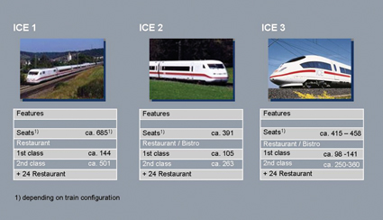

Figure 1: Features of the ICE trains
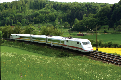

Figure 2: ICE S
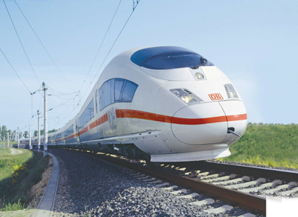

Figure 3: ICE 3
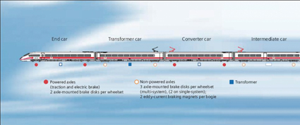

Figure 4: Design of the ICE 3


Figure 5: Panoramic views of the route


Figure 6: Passenger information system on the ICE 3


Figure 7: Design of the Velaro
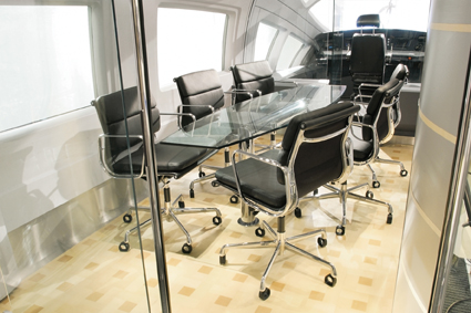

Figure 9: Club Lounge in the Velaro E
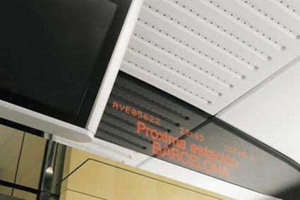

Figure 10: Passenger information system
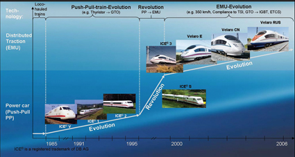

Figure 11: Evolution of the Velaro high speed platform: from power car to distributed traction
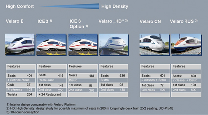

Figure 12: Features of the high speed platform
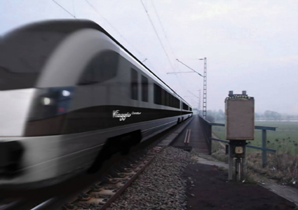

Figure 13: Design study of Viaggio Comfort
References
- Petrovitsch, H.: Das Shinkansen-Hochgeschwindigkeits-Netz in Japen; published in: Eisenbahn-Revue International 7/02, p. 320
- Henn, W.; Herrmann, H.; Hochbruck, H.: Hochgeschwindigkeitsverkehr in Deutschland; Published in: ICE – Zug der Zukunft, pp. 34 – 89.
- ICE-Chronik; published in: ICE T BR 411, 415 & 605.
- Müller, C.: Der ICE 1 wird neu; published in: Eisenbahningenieur 8/2005, pp. 54 – 57.
- Lößel, W.; Prem, J.; Landwehr, H: ICE 3 – Die neue Generation der europäischen Hochgeschwindigkeitszüge; published in: ICE – Zug der Zukunft, pp. 147 – 171.
- Präsentation des neuen DB-Versuchszuges ICE-S; published in: Eisenbahn 1/1998.
- Anmerkungen zu den Versuchs-ICE; published in: LOK Report, 09.02.2005.
- Konrad, H.; Nahmer, S.: „ICE S“ Ein Versuchszug für den ICE 3; published in: Eisenbahn-Kurier 9/97, pp. 30 – 33.
- Gerhard, T.: Neuentwicklungen für den ICE 3 ®; published in: ETR, 7/8/1997, pp. 427 – 432.
- Gerhard, T.; Karch, S.: Moderne Triebzüge für den Fernverkehr – eine Systembetrachtung; Veröffentlichung in: Jahrbuch des Bahnwesens Nah- und Fernverkehr, Folge 49-2000, pp. 60 – 71.
- Budzinski, F.; Fischer, J.; Markowetz, H.: Elektrische Ausrüstung des Hochgeschwindigkeitzuges Velaro E; published in: eb 3/2004, pp. 99 – 108.
About the authors
Dr. Ing. Ansgar Brockmeyer completed studies in Electrical Engineering at RWTH Aachen, doctorate at the RWTH department of power converters and electrical drives and has been working in different positions for the Transportation Systems Group of Siemens AG since 1997. His last position was head of the onboard power supply subdivision and he has been head of the Trains division since 2006.
Dipl.-Ing. Manfred Reisner graduated from Mining University Leoben in 1988 with a diploma degree in Petroleum Engineering. He joined SGP AG (later acquired by Siemens AG) in 1991 and has been working in different positions in Sales and Project Management for Passenger Coaches worldwide. Since 2000 he has been Head of Sales and Marketing subdivision Passenger Coaches (TS TR PC)
Dipl.-Ing. Thomas Gerhard completed studies in Mechanical Engineering at Fachhochschule Niederrhein, 1976 – 1994 employed with Wagonfabrik Uerdingen / DUEWAG AG in various positions, including head of technical sales for main-line trains and has been working in various positions for the Trains division of the Transportation Systems Group of Siemens AG since 1994. His last position was as head of Engineering Trains and he has now been head of Group Technology of the Transportation Systems Group since 2006.
Dipl.-Ing. Monika Bayrhof completed studies in Electrical Engineering at Technical University Munich, 2003 – 2005 participant of international graduate program at Siemens with positions in Sales and Project Management for Transportation Systems group of Siemens AG. Since 2005, Monika Bayrhof has been the Personal Assistant to Divisional Management Transportations Systems Trains.
Dipl.-Ing. Edzard Lübben completed studies in Mechanical Engineering at RWTH Aachen and MIT in Cambridge, USA. He has been working in various positions for the Trains division of the Transportation Systems Group of Siemens AG since 2003. He has been Head of Sales and Marketing subdivision, Projects High Speed and Intercity Trains (TS TR HI) since 2006.
Global Railway Review Autumn/ Winter Issue 2025
Welcome to 2025’s Autumn/ Winter issue of Global Railway Review!
The dynamism of our sector has never been more apparent, driven by technological leaps, evolving societal demands, and an urgent global imperative for sustainable solutions.
>>> Read the issue in full now! <<<




This paper of high-speed trains is very good to read and understand.