New development stage of RHEDA 2000®
Posted: 15 May 2009 | | No comments yet
Jens Kleeberg, Vice President of R&D, RAIL.ONE GmbH, discusses the next step in the development of ballastless track.


Jens Kleeberg, Vice President of R&D, RAIL.ONE GmbH
High-speed rail traffic – and, consequently, regularly scheduled train service at speeds over 230km/h – has demonstrated tremendous development since its beginnings in the late 1970s, and above all during recent years. The required rail lines, as well as interconnected high-speed rail networks have been vigorously and continuously expanded, especially in Asia and in Europe. As part of this process, the entire complex of railway technology has been further developed on an uninterrupted basis and has been adapted to the more demanding requirements encountered: with respect to rolling stock, train traffic control and supervision systems, and – not least – track technology. It is therefore unsurprising that not only the very latest in trains are using the new high-speed networks, but that the state-of-the-art in track technology is also being likewise implemented.
As part of this overall pattern, the following development has also become apparent; that so-called ballastless track is being installed instead of conventional ballasted track, in sections of entire track lines as well as on the entire lengths of high-speed routes. From the great number of track concepts being implemented, and in addition to systems with precast slab segments, the Rheda systems (and especially the RHEDA 2000® ballastless track system) have proved to be especially advantageous for the high-speed area of application. The RHEDA 2000® is the further development of a ballastless track design that was installed for the first time in 1972 as a pilot section on the line from Bielefeld to Hamm, at the Rheda train station in Lower Saxony, Germany. Since 2000, the RHEDA 2000® design type in its present form, as well as other RHEDA technology types, have been installed in more than 10 countries, over more than 2,000km of track, and with over 200 turnouts and rail expansion joints.
Development steps and track system design for the RHEDA 2000® ballastless track
Throughout its development until now, the RHEDA system has retained two prime characteristics:
- The track system design consists of a track panel made of rails connected by highly elastic rail fastenings to traverse sleepers. In standard models, this track is permanently fixed in position by means of a concrete slab (requiring no maintenance) supported by various substructures or supporting layers
- For track installation and during concreting of the track-supporting layer, the track panel of rails and sleepers is adjusted in its position directly at the rail, at which surveying alignment also takes place. Together with use of highly precisely manufactured sleepers, this so-called top-down installation process assures the track-geometry quality required for high-speed train traffic
In comparison to the original RHEDA design, the RHEDA 2000® has been enhanced in two essential aspects; to the extent that the risks of the system have been reduced to a non-critical degree – without impairing the economy, the reliability, and the safety of the system:
- RHEDA 2000® has only one monolithic concrete track-supporting layer (i.e., monolithic in that it is created in one concrete-casting process). This design eliminates the risk of formation of a gaping and progressive crack between the old trough (concrete upstands) and the concrete track-supporting layer. This mechanism had earlier led to permanent damage, especially with the Rheda variants with trough-shaped track-supporting layer
- In addition, employment of non-prestressed, modified bi-block sleepers has likewise improved the bond between the concrete track-supporting layer and the sleepers – and has furthermore prevented the systematic loosening that had earlier occurred in monoblock sleepers by shrinkage in the concrete track-supporting layer. Until now, systematic sleeper loosening or critical cracking at the contact surfaces has not appeared in any track with these modified bi-block sleepers
The advantages of the RHEDA 2000® system until now
Today, RHEDA 2000® – after more than 35 years of operational experience of the pilot system, as well as almost 10 years in the latest evolution stage – can be considered as technically mature and, therefore, controllable. The application of RHEDA 2000® in numerous European and Asian countries emphasises the flexibility of the system, with respect to various types of rolling stock, subgrade conditions, and climates. This has become especially apparent in employment of RHEDA 2000® for operation of all three widely used high-speed international train systems: the Shinkansen for Taiwan HSR, the TGV in applications including the Netherlands, and the ICE in Germany and elsewhere. RHEDA 2000® is likewise used in conjunction with various and different signal systems, including ETCS, Track Circuit and LZB.
The prime advantage of RHEDA 2000®, however, lies in its exceptionally simple, end-to-end system design, highly effective as it is for main-track and turnout areas and on various types of substructures and substrates. As a result, RHEDA 2000® track can be installed by virtually any construction company, without the use of special machines. A special advantage is that local construction companies are effectively able to install RHEDA 2000®.
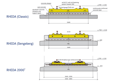

Figure 1: The stages of development of RHEDA technology become evident when comparing the various track cross-sections
Modification of RHEDA 2000®
Just as the original ballastless track at Rheda station in Germany, the RHEDA 2000® also consists of a track panel fixed in a reinforced concrete slab. For installation on embankments, the concrete track-supporting layer is executed in continuous form i.e., without joints. An additional bound support layer, normally with cement solidification under the permanent way, is installed to reduce tensile stresses in the track supporting layer and compressive stresses in the soil. The dimensions of the bound supporting layers depend on the stiffness at the surface of the embankment, in addition to the train axle loads. Normally, the dimensions shown in Figure 2 will apply for a compacted embankment with additional soil improvement layer.
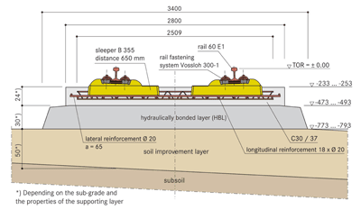

Figure 2: Cross section of RHEDA 2000 on embankments
On account of the slight environmental influence to which it is subjected, the track sublayer does not require reinforcement. To achieve regular, controlled crack formation, the sublayer should be notched at intervals of approximately 5m. The concrete track supporting layer, on the other hand, is allowed to freely develop cracks. The intervals between cracks and the extent of crack expansion that arise here will depend on the percentage of reinforcement and the concrete tensile strength. For the RHEDA 2000® standard structural design shown in Figure 2, the ideal design solution is one layer of longitudinal reinforcement (installed in the centre and over the height of the concrete slab) with a share of approximately 0.8 to 0.9% of the concrete cross-section1, and with reinforcing bar diameter of at least 16mm. This would allow restriction of crack width to 0.5mm, proved to be harmless from the context of motorway construction, as well as reduction to a noncritical degree, by sufficient transfer of lateral forces, of the tension occurring at the edges of the cracks.
For both motorways as well as for railway track, continuously produced concrete track without expansion joints has been sufficiently tried and proven by now and represents the state-of-the-art. However, one risk of this design is the considerable longitudinal tensile stresses in the concrete track-supporting layer. Since expansion joints are not provided in this layer, significant constraints arise owing to shrinkage and cooling of the supporting layer (both from release of heat of hydration and from ambient temperature drop). These constraints regularly lead to cracking of the concrete layer. Once these cracks are subject to direct environmental effects, they must be reduced to a degree that is harmless for the concrete layer and for its reinforcement. As a result, complete stress relief of the concrete layer does not take place. The prime consequence here, at low temperatures, is appreciable tensile stress in the supporting layer, forces that, in addition to live train loads, must also be borne by the concrete supporting layer.
RHEDA 2000® without reinforcement
In addition to the variant described above with continuous concrete supporting layer, motorways are frequently constructed today throughout the world with controlled formation of cracks. In this process, the concrete layer is generally weakened at an early stage of the concrete hardening process by cutting through or notching the cross-section at regular intervals. As a result, stress-relief cracks arise only at these planned points during the cooling and hardening of the concrete. To prevent the staggered formation that frequently occurs at the cracks as a result of operational loading, lateral anchors must be installed. Since, however, these anchors do not limit crack width, they are coated with a synthetic layer as protection from corrosion. As a final step, a compound is poured into the crack to prevent frost damage. The concrete track-supporting layer is dimensioned in such a way that the tensile stresses can be effectively borne by the concrete, and that no reinforcement whatsoever is required in the concrete layer.
The essential difference is the continuous reinforcement for the freely cracking system versus the crack inducers in parallel with the shear dowels for the other system.
The most recent development stage of RHEDA 2000® applies the technology described above to ballastless tracks. The modified RHEDA 2000® system therefore consists of a non-reinforced concrete supporting layer with controlled formation of cracks. The desired induction of cracks is produced by steel blades that are adjusted to the installed rails and that extend approximately one-third of the way into the concrete cross-section. The lateral anchors are installed on the lattice trusses of the sleepers. Figure 4 also shows the required configuration before concreting the system.
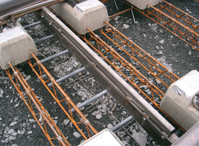

Figure 4: RHEDA 2000 as installed, with controlled crack formation
The modified system can be customised in various ways to optimally match it to the required application, in accordance with the loads being borne, the quality of the concrete of the supporting layer, and the degree of compaction of the earth below. Two basic versions have been designed for axle loads up to 25 metric tonnes – the following models are scheduled for field testing on a track in the near future:
Variant with cement-stabilised subbase
This version is supported by a subbase with bearing capacity of approximately 120 MN/m² (load circle of 150mm). With stable underground conditions, this bearing capacity can be achieved by sufficient compaction of soil, in conjunction with an additional highly compacted soil improvement layer, or also by a frost protection layer (FPL). The dimensions of the track in this context are primarily determined by the pressure load subjected to the subbase, as well as by the tensile stresses in the lower supporting layer (HBL), which is stabilised only slightly with cement. The tensile stresses in the concrete track-supporting layer are significantly less than those in continuously reinforced systems. For structural design reasons, however, no further attempts have been made to optimise this concrete layer (e.g., by integrating the sleepers). A significant advantage of this system with controlled crack formation results, nevertheless, since it minimises the risk of weakening the track-supporting layer by cracks. For the conditions as stated above and for axle loads of 25 metric tonnes, thicknesses of 24cm result for the track concrete layer (TCL), and of 30cm for the hydraulically bound support layer (HBL). The concrete grade of the TCL should be C30/37 in accordance with EN 206, whereby air entraining agents are be required to enhance durability under conditions of frost effects in combination with long-term use of de-icing salt.
This model is a cost-effective variant in the design of track substructures and superstructures. In addition, this solution places no extreme special demands on the individual supporting layers, and is accordingly feasible anywhere without difficulty on normally consolidated soils.
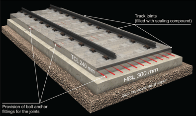

Figure 5: RHEDA 2000 with controlled formation of cracks, on a cement stabilised sub-base (HBL)
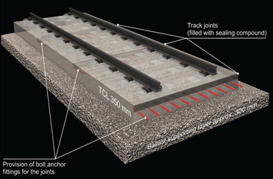

Figure 6: RHEDA 2000 with controlled crack formation, on a ballast sub-base (BSL)
Variant with ballast subbase
A ballast subbase is understood as a non-bound but high-strength supporting layer. It achieves its stiffness and load-bearing capacity by the quality, the form, and the composition of the ballast stone used. As a result, only crushed stone with great strength and with optimal interlocking geometries is used here. In addition, these supporting layers are composed of a stone mixture with a special grading curve similar to the bound supporting layers. This allows a load-bearing capacity of 150 to 180 MN/m², which allows for extremely great compressive stresses at the ballast surfaces.
With use of such subbase, the track concrete layer (TCL) of RHEDA 2000® can be directly applied onto the subbase, without use of a further bound layer. The TCL, however, must be installed only with a thickness of 35cm, for axle loads of 25 metric tonnes at 150 MN/m². The concrete quality, furthermore, should be increased to C35/45 in accordance with EN 206, for the necessary increase in tensile strength. No air entraining agents are necessary here, even with use of de-icing salt.
This variant represents the cross-section that presently offers the least possible use of material. For this reason, and in conjunction with the associated simplification of the construction process, this solution offers the greatest cost-saving potentials. As a result, it is capable of further appreciable reduction in the unavoidable cost difference between classical ballasted tracks and ballastless track systems. Although the non-bound supporting layer represents a special design with this mode of construction, its implementation also represents no risk when the proper raw materials and construction equipment are employed.
Comparison of RHEDA 2000® with and without reinforcement
A comparison between the reinforced RHEDA 2000® system with continuous reinforcement and, accordingly, with unconstrained crack formation, and the modified RHEDA 2000® system without reinforcement and with controlled crack formation, clearly reveals the advantages of the latter solution. The prime differences and associated benefits are as follows:
Enhanced cost-effectiveness
In all variant models, the system with controlled crack formation is implemented without reinforcement of any kind. The required synthetic-coated anchors represent a far smaller investment that the otherwise necessary longitudinal and lateral reinforcement. In addition, the short (50cm) anchors can be installed with considerably less effort, with the result that the steps of work otherwise necessary, with great expenditure of manual labour, are practically eliminated. The variant with ballast sublayer (BSL) is installed without a bound supporting layer and therefore offers a maximum of savings in required materials and necessary installation labour.
Improved technological system and the associated reduction in risk
The system with controlled crack formation features a substantially lower intrinsic-stress level in the track concrete layer (TCL) than does the system with continuous reinforcement. Since the effects of traffic and environment meet here to a maximum degree, the risk of entirely eliminating the reinforcement is overcompensated by the considerably lesser overall stress level. The result is an economically more favourable and, therefore, superior system.
Appreciable simplification of electromagnetic interactions
The operation of train traffic control and supervision systems subjects track rails to electromagnetic fields. When concentrated masses of steel are associated with these fields, the functioning of such control and supervision systems can be seriously impaired. Concrete tracks with continuous reinforcement must be critically considered from the standpoint of earthing engineering. In addition, they entail capacitance and impedance levels that can render certain signal systems inoperable. RHEDA 2000® technically compensates for these two effects, but effective countermeasures are required. Elimination of the reinforcement signifies that the system in this context is equally effective, at the very least, as ballasted track, and that it is compatible with signalling systems to an unrestricted degree. With respect to earthing, the required systems are either much reduced in extent, or entirely unnecessary, depending on requirements.
Maximum flexibility for adaptation to soil conditions
The reduced stress levels in the track concrete layer (TCL) allow the system to be installed on a wide range of strength in embankment conditions. Weaker subgrade conditions can be used to support the system, without additional expense for concrete, reinforcement, etc. With high-quality subcourse conditions, the savings potentials described above will apply.
Further development steps
In order to develop the modified system to series-production readiness, the following investigations have been planned:
Field testing
To achieve series-production readiness, the modified system is scheduled to be installed as operational track in 2009 or 2010. Currently, two possible applications have been considered for implementation; in mass rapid transit, and in standard-gauge railway use with freight trains. Owing to the extensive experience gained in roadway construction, and with the existing RHEDA 2000® system, these measures are not actually intended to represent field testing, but rather the final step toward gaining the practice necessary for large-scale application.
Further development of the system for use with turnouts
In order to obtain the benefits of the system in turnout applications as well, a solution appropriate for this application is being developed. Initial engineering draft concepts already exist, and will be further developed in the near future.
Further development of the system for use with bridges
To avoid system changes, variants for bridges are urgently necessary. Concerted efforts along this development will be pursued, as with the technology for turnouts.
Summary
RHEDA 2000® is one of the few ballastless-track technologies that has by now achieved maturity. The system has now been successfully employed in more than 10 countries, and will in the future continue to represent a reliable, safe, and cost-effective solution for railway track construction. In the course of very many applications, the system had already been expanded and improved in many and various contexts, which has led to a great degree of flexibility and application versatility.
The RHEDA 2000® system, however, still offers further potential for fundamental improvements. The possibility of controlled instead of free crack formation, for example, offers numerous advantages which extend from improved economy, to simplified installation, and to greater safety by reduced loads applied to material. After brief investigation of the modified system in practice, it could well become a new standard – first on embankments and later in the area of turnouts and on other supporting structures such as bridges.
Reference
- Eisenmann Josef, Leykauf Günther: special printing from Beton-Kalender 2000 – Feste Fahrbahn für Schienenbahnen. Ernst & Sohn Verlag für Architektur und technische Wissenschaften GmbH, Berlin, 2000.
High-speed rail traffic – and, consequently, regularly scheduled train service at speeds over 230km/h – has demonstrated tremendous development since its beginnings in the late 1970s, and above all during recent years. The required rail lines, as well as interconnected high-speed rail networks have been vigorously and continuously expanded, especially in Asia and in Europe. As part of this process, the entire complex of railway technology has been further developed on an uninterrupted basis and has been adapted to the more demanding requirements encountered: with respect to rolling stock, train traffic control and supervision systems, and – not least – track technology. It is therefore unsurprising that not only the very latest in trains are using the new high-speed networks, but that the state-of-the-art in track technology is also being likewise implemented.
As part of this overall pattern, the following development has also become apparent; that so-called ballastless track is being installed instead of conventional ballasted track, in sections of entire track lines as well as on the entire lengths of high-speed routes. From the great number of track concepts being implemented, and in addition to systems with precast slab segments, the Rheda systems (and especially the RHEDA 2000® ballastless track system) have proved to be especially advantageous for the high-speed area of application. The RHEDA 2000® is the further development of a ballastless track design that was installed for the first time in 1972 as a pilot section on the line from Bielefeld to Hamm, at the Rheda train station in Lower Saxony, Germany. Since 2000, the RHEDA 2000® design type in its present form, as well as other RHEDA technology types, have been installed in more than 10 countries, over more than 2,000km of track, and with over 200 turnouts and rail expansion joints.
Development steps and track system design for the RHEDA 2000® ballastless track
Throughout its development until now, the RHEDA system has retained two prime characteristics:
1. The track system design consists of a track panel made of rails connected by highly elastic rail fastenings to traverse sleepers. In standard models, this track is permanently fixed in position by means of a concrete slab (requiring no maintenance) supported by various substructures or supporting layers
2. For track installation and during concreting of the track-supporting layer, the track panel of rails and sleepers is adjusted in its position directly at the rail, at which surveying alignment also takes place. Together with use of highly precisely manufactured sleepers, this so-called top-down installation process assures the track-geometry quality required for high-speed train traffic
In comparison to the original RHEDA design, the RHEDA 2000® has been enhanced in two essential aspects; to the extent that the risks of the system have been reduced to a non-critical degree – without impairing the economy, the reliability, and the safety of the system:
a) RHEDA 2000® has only one monolithic concrete track-supporting layer (i.e., monolithic in that it is created in one concrete-casting process). This design eliminates the risk of formation of a gaping and progressive crack between the old trough (concrete upstands) and the concrete track-supporting layer. This mechanism had earlier led to permanent damage, especially with the Rheda variants with trough-shaped track-supporting layer
b) In addition, employment of non-prestressed, modified bi-block sleepers has likewise improved the bond between the concrete track-supporting layer and the sleepers – and has furthermore prevented the systematic loosening that had earlier occurred in monoblock sleepers by shrinkage in the concrete track-supporting layer. Until now, systematic sleeper loosening or critical cracking at the contact surfaces has not appeared in any track with these modified bi-block sleepers
The advantages of the RHEDA 2000® system until now
Today, RHEDA 2000® – after more than 35 years of operational experience of the pilot system, as well as almost 10 years in the latest evolution stage – can be considered as technically mature and, therefore, controllable. The application of RHEDA 2000® in numerous European and Asian countries emphasises the flexibility of the system, with respect to various types of rolling stock, subgrade conditions, and climates. This has become especially apparent in employment of RHEDA 2000® for operation of all three widely used high-speed international train systems: the Shinkansen for Taiwan HSR, the TGV in applications including the Netherlands, and the ICE in Germany and elsewhere. RHEDA 2000® is likewise used in conjunction with various and different signal systems, including ETCS, Track Circuit and LZB.
The prime advantage of RHEDA 2000®, however, lies in its exceptionally simple, end-to-end system design, highly effective as it is for main-track and turnout areas and on various types of substructures and substrates. As a result, RHEDA 2000® track can be installed by virtually any construction company, without the use of special machines. A special advantage is that local construction companies are effectively able to install RHEDA 2000®.


Modification of RHEDA 2000®
Just as the original ballastless track at Rheda station in Germany, the RHEDA 2000® also consists of a track panel fixed in a reinforced concrete slab. For installation on embankments, the concrete track-supporting layer is executed in continuous form i.e., without joints. An additional bound support layer, normally with cement solidification under the permanent way, is installed to reduce tensile stresses in the track supporting layer and compressive stresses in the soil. The dimensions of the bound supporting layers depend on the stiffness at the surface of the embankment, in addition to the train axle loads. Normally, the dimensions shown in Figure 2 will apply for a compacted embankment with additional soil improvement layer.


On account of the slight environmental influence to which it is subjected, the track sublayer does not require reinforcement. To achieve regular, controlled crack formation, the sublayer should be notched at intervals of approximately 5m. The concrete track supporting layer, on the other hand, is allowed to freely develop cracks. The intervals between cracks and the extent of crack expansion that arise here will depend on the percentage of reinforcement and the concrete tensile strength. For the RHEDA 2000® standard structural design shown in Figure 2, the ideal design solution is one layer of longitudinal reinforcement (installed in the centre and over the height of the concrete slab) with a share of approximately 0.8 to 0.9% of the concrete cross-section1, and with reinforcing bar diameter of at least 16mm. This would allow restriction of crack width to 0.5mm, proved to be harmless from the context of motorway construction, as well as reduction to a noncritical degree, by sufficient transfer of lateral forces, of the tension occurring at the edges of the cracks.
For both motorways as well as for railway track, continuously produced concrete track without expansion joints has been sufficiently tried and proven by now and represents the state-of-the-art. However, one risk of this design is the considerable longitudinal tensile stresses in the concrete track-supporting layer. Since expansion joints are not provided in this layer, significant constraints arise owing to shrinkage and cooling of the supporting layer (both from release of heat of hydration and from ambient temperature drop). These constraints regularly lead to cracking of the concrete layer. Once these cracks are subject to direct environmental effects, they must be reduced to a degree that is harmless for the concrete layer and for its reinforcement. As a result, complete stress relief of the concrete layer does not take place. The prime consequence here, at low temperatures, is appreciable tensile stress in the supporting layer, forces that, in addition to live train loads, must also be borne by the concrete supporting layer.


RHEDA 2000® without reinforcement
In addition to the variant described above with continuous concrete supporting layer, motorways are frequently constructed today throughout the world with controlled formation of cracks. In this process, the concrete layer is generally weakened at an early stage of the concrete hardening process by cutting through or notching the cross-section at regular intervals. As a result, stress-relief cracks arise only at these planned points during the cooling and hardening of the concrete. To prevent the staggered formation that frequently occurs at the cracks as a result of operational loading, lateral anchors must be installed. Since, however, these anchors do not limit crack width, they are coated with a synthetic layer as protection from corrosion. As a final step, a compound is poured into the crack to prevent frost damage. The concrete track-supporting layer is dimensioned in such a way that the tensile stresses can be effectively borne by the concrete, and that no reinforcement whatsoever is required in the concrete layer.
The essential difference is the continuous reinforcement for the freely cracking system versus the crack inducers in parallel with the shear dowels for the other system.
The most recent development stage of RHEDA 2000® applies the technology described above to ballastless tracks. The modified RHEDA 2000® system therefore consists of a non-reinforced concrete supporting layer with controlled formation of cracks. The desired induction of cracks is produced by steel blades that are adjusted to the installed rails and that extend approximately one-third of the way into the concrete cross-section. The lateral anchors are installed on the lattice trusses of the sleepers. Figure 4 also shows the required configuration before concreting the system.


The modified system can be customised in various ways to optimally match it to the required application, in accordance with the loads being borne, the quality of the concrete of the supporting layer, and the degree of compaction of the earth below. Two basic versions have been designed for axle loads up to 25 metric tonnes – the following models are scheduled for field testing on a track in the near future:
Variant with cement-stabilised subbase
This version is supported by a subbase with bearing capacity of approximately 120 MN/m² (load circle of 150mm). With stable underground conditions, this bearing capacity can be achieved by sufficient compaction of soil, in conjunction with an additional highly compacted soil improvement layer, or also by a frost protection layer (FPL). The dimensions of the track in this context are primarily determined by the pressure load subjected to the subbase, as well as by the tensile stresses in the lower supporting layer (HBL), which is stabilised only slightly with cement. The tensile stresses in the concrete track-supporting layer are significantly less than those in continuously reinforced systems. For structural design reasons, however, no further attempts have been made to optimise this concrete layer (e.g., by integrating the sleepers). A significant advantage of this system with controlled crack formation results, nevertheless, since it minimises the risk of weakening the track-supporting layer by cracks. For the conditions as stated above and for axle loads of 25 metric tonnes, thicknesses of 24cm result for the track concrete layer (TCL), and of 30cm for the hydraulically bound support layer (HBL). The concrete grade of the TCL should be C30/37 in accordance with EN 206, whereby air entraining agents are be required to enhance durability under conditions of frost effects in combination with long-term use of de-icing salt.
This model is a cost-effective variant in the design of track substructures and superstructures. In addition, this solution places no extreme special demands on the individual supporting layers, and is accordingly feasible anywhere without difficulty on normally consolidated soils.


Variant with ballast subbase
A ballast subbase is understood as a non-bound but high-strength supporting layer. It achieves its stiffness and load-bearing capacity by the quality, the form, and the composition of the ballast stone used. As a result, only crushed stone with great strength and with optimal interlocking geometries is used here. In addition, these supporting layers are composed of a stone mixture with a special grading curve similar to the bound supporting layers. This allows a load-bearing capacity of 150 to 180 MN/m², which allows for extremely great compressive stresses at the ballast surfaces.
With use of such subbase, the track concrete layer (TCL) of RHEDA 2000® can be directly applied onto the subbase, without use of a further bound layer. The TCL, however, must be installed only with a thickness of 35cm, for axle loads of 25 metric tonnes at 150 MN/m². The concrete quality, furthermore, should be increased to C35/45 in accordance with EN 206, for the necessary increase in tensile strength. No air entraining agents are necessary here, even with use of de-icing salt.
This variant represents the cross-section that presently offers the least possible use of material. For this reason, and in conjunction with the associated simplification of the construction process, this solution offers the greatest cost-saving potentials. As a result, it is capable of further appreciable reduction in the unavoidable cost difference between classical ballasted tracks and ballastless track systems. Although the non-bound supporting layer represents a special design with this mode of construction, its implementation also represents no risk when the proper raw materials and construction equipment are employed.
Comparison of RHEDA 2000® with and without reinforcement
A comparison between the reinforced RHEDA 2000® system with continuous reinforcement and, accordingly, with unconstrained crack formation, and the modified RHEDA 2000® system without reinforcement and with controlled crack formation, clearly reveals the advantages of the latter solution. The prime differences and associated benefits are as follows:
Enhanced cost-effectiveness
In all variant models, the system with controlled crack formation is implemented without reinforcement of any kind. The required synthetic-coated anchors represent a far smaller investment that the otherwise necessary longitudinal and lateral reinforcement. In addition, the short (50cm) anchors can be installed with considerably less effort, with the result that the steps of work otherwise necessary, with great expenditure of manual labour, are practically eliminated. The variant with ballast sublayer (BSL) is installed without a bound supporting layer and therefore offers a maximum of savings in required materials and necessary installation labour.
Improved technological system and the associated reduction in risk
The system with controlled crack formation features a substantially lower intrinsic-stress level in the track concrete layer (TCL) than does the system with continuous reinforcement. Since the effects of traffic and environment meet here to a maximum degree, the risk of entirely eliminating the reinforcement is overcompensated by the considerably lesser overall stress level. The result is an economically more favourable and, therefore, superior system.
Appreciable simplification of electromagnetic interactions
The operation of train traffic control and supervision systems subjects track rails to electromagnetic fields. When concentrated masses of steel are associated with these fields, the functioning of such control and supervision systems can be seriously impaired. Concrete tracks with continuous reinforcement must be critically considered from the standpoint of earthing engineering. In addition, they entail capacitance and impedance levels that can render certain signal systems inoperable. RHEDA 2000® technically compensates for these two effects, but effective countermeasures are required. Elimination of the reinforcement signifies that the system in this context is equally effective, at the very least, as ballasted track, and that it is compatible with signalling systems to an unrestricted degree. With respect to earthing, the required systems are either much reduced in extent, or entirely unnecessary, depending on requirements.
Maximum flexibility for adaptation to soil conditions
The reduced stress levels in the track concrete layer (TCL) allow the system to be installed on a wide range of strength in embankment conditions. Weaker subgrade conditions can be used to support the system, without additional expense for concrete, reinforcement, etc. With high-quality subcourse conditions, the savings potentials described above will apply.
Further development steps
In order to develop the modified system to series-production readiness, the following investigations have been planned:
Field testing
To achieve series-production readiness, the modified system is scheduled to be installed as operational track in 2009 or 2010. Currently, two possible applications have been considered for implementation; in mass rapid transit, and in standard-gauge railway use with freight trains. Owing to the extensive experience gained in roadway construction, and with the existing RHEDA 2000® system, these measures are not actually intended to represent field testing, but rather the final step toward gaining the practice necessary for large-scale application.
Further development of the system for use with turnouts
In order to obtain the benefits of the system in turnout applications as well, a solution appropriate for this application is being developed. Initial engineering draft concepts already exist, and will be further developed in the near future.
Further development of the system for use with bridges
To avoid system changes, variants for bridges are urgently necessary. Concerted efforts along this development will be pursued, as with the technology for turnouts.
Summary
RHEDA 2000® is one of the few ballastless-track technologies that has by now achieved maturity. The system has now been successfully employed in more than 10 countries, and will in the future continue to represent a reliable, safe, and cost-effective solution for railway track construction. In the course of very many applications, the system had already been expanded and improved in many and various contexts, which has led to a great degree of flexibility and application versatility.
The RHEDA 2000® system, however, still offers further potential for fundamental improvements. The possibility of controlled instead of free crack formation, for example, offers numerous advantages which extend from improved economy, to simplified installation, and to greater safety by reduced loads applied to material. After brief investigation of the modified system in practice, it could well become a new standard – first on embankments and later in the area of turnouts and on other supporting structures such as bridges.
Reference
1. Eisenmann Josef, Leykauf Günther: special printing from Beton-Kalender 2000 – Feste Fahrbahn für Schienenbahnen. Ernst & Sohn Verlag für Architektur und technische Wissenschaften GmbH, Berlin, 2000.


