MVDC-ERS: The next generation of railway electrification systems
Posted: 13 May 2021 | Pietro Tricoli, Sina Sharifi | No comments yet
Pietro Tricoli, Head of the Power Electronics Group at the Birmingham Centre for Railway Research and Education (BCRRE), and Sina Sharifi, member of the BCRRE, explain how the Flexible Medium Voltage DC Electric Railway Systems (MVDC-ERS) project aims to explore how medium voltage DC technology can be applied to railway electrification systems.


Railway electrification provides faster and more reliable train journeys when compared to diesel trains, as well as a strong reduction of pollution in busy stations and the countryside. However, many national programmes for the electrification of new and existing railway lines have required a substantial investment in the railway infrastructure. One of the reasons is because railway electrification uses AC single-phase power that requires a connection to high-voltage transmission lines, which are not always available in the intended locations of railway feeder stations and, usually, require complicated and extremely expensive modifications of the existing layouts, e.g. tap and looped connections of the substations.
Additionally, new electric railways introduce intermittent load peaks that might affect the stability of the grid, especially for future scenarios where the inertia of the power system will be substantially reduced for the widespread adoption of renewable power sources. To facilitate the integration of renewable sources and increase the efficiency of the power distribution, there is currently a significant interest in medium voltage DC power distribution grids. The Flexible Medium Voltage DC Electric Railway Systems (MVDC-ERS) project investigates how medium voltage DC technology can be applied to railway electrification systems.
Overall concept
The typical power level of heavy railways, and even high-speed railways, are in the range of 100- 500 MVA, with individual supply points designed for a peak power of 50-100 MVA, which is compatible with the typical capabilities of medium-voltage distribution systems. However, for AC railways, the connection of railway feeder stations to the power distribution network would be possible only by adopting schemes that introduce only a very limited imbalance.
Traditional low voltage DC power supplies satisfy this requirement, as the DC voltage is generated by a three-phase diode rectifier that draws balanced current with high power factor. However, the maximum level of the DC voltage is 3kV for the limitation on the maximum short-circuit breaking current of DC circuit breakers. This, in turn, limits the maximum power of each traction power substation (TPS) to a few megawatts (MW) and the maximum distance between substations to a few kilometres (km). Additionally, a higher voltage of the DC power supply would pose problems for the traction system of the trains, which operates at voltage levels of a few kilovolts (kV). Moreover, the traditional concept of DC railways does not fit very well with the future vision of electric railways, which are better integrated with the power distribution networks, as the diode rectifiers are unidirectional and the power factor depends on the load inductance, and this prevents any control of the power flows and the power quality.
To address these challenges, MVDC-ERS proposes a new Medium Voltage DC (MVDC) traction power supply based on controlled bidirectional converters. In this system, medium‑voltage multilevel converters are used in the TPSs to connect the MVDC railway to the power distribution grid. These converters are based on individual building blocks (submodules), operating at around 3.3-6.5kV, that can be stacked in series to reach the desired level for the DC voltage. The converters can regulate the DC side voltage at the nominal value within a broad load range and limit the current during DC short circuit events. This means that the MVDC system can be implemented with DC circuit breakers designed for the nominal current or a value slightly higher than that, which are simpler and cheaper than high‑current MVDC circuit breakers.
With reference to the on-board traction systems, the main challenge of MVDC electrification is to find suitable alternatives to transformers to step-down the voltage to levels compatible with traction inverters and motors. To address this challenge, DC PETTs can be used to replace the traditional low frequency transformers. DC PETTs are medium-voltage DC-DC converters which utilise medium‑frequency transformers and, hence, achieve a higher power-density and efficiency.
The converters used in both TPSs and trains for MVDC electrification systems will also benefit significantly from the introduction of wide band‑gap semiconductor devices, like silicon carbide and gallium nitride, as the higher blocking voltages will lead to simpler topologies, and the higher switching frequencies will lead to higher power densities and higher energy efficiency.
The possibility of controlling the power flow between the power distribution and the electrification networks opens new scenarios for the interaction with the grid. In fact, the railway can be mesh fed, reducing the peak power of individual TPSs, without the risk of power circulation in parallel to the grid. An example is provided in Figure 1, indicating a section of the railway supplied by two feeder stations with in-situ renewable power sources. Depending on the traffic conditions, the railway can be operated to mitigate heavy traction loads using renewable sources, to reduce the power from the grid when there are light loads on the railway, to maximise the recuperation of regenerative braking and to support distant nodes of the power distribution network using the electrification line as a parallel path, mitigating constraints on the grid.
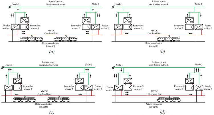

FIGURE 1: VARIOUS OPERATIONAL MODES IN MVDC ELECTRIFICATION SYSTEM: (A) HEAVY TRAFFIC CONDITION, (B) LIGHT TRAFFIC CONDITION, (C) REGENERATIVE BRAKING, (D) SUPPORTING POWER DISTRIBUTION GRID.
In summary, the main research objectives of MVDC-ERS are:
- To introduce new high-efficiency topologies of power conversion systems to convert medium‑voltage AC power into medium-voltage DC power with the capability of limiting the DC short circuit current
- To introduce high-power density topologies of power converters for on-board DC transformers
- To investigate the impact of the forthcoming wide band-gap semiconductor devices in terms of efficiency and voltage level for the converters of the feeder stations, and in terms of weight and volume for the traction converters
- To understand how the new railway electrification system should be controlled and protected when renewable power sources are integrated
- To understand how energy storage systems can be used to optimise the operations of the railway electrification network
- To work with industrial stakeholders to investigate the marketability of the new electrification system and trains.
Advantages of MVDC-ERS
The MVDC system benefits from the following advantages over conventional single-phase AC electrification systems:
- The MVDC system draws balanced currents from the distribution network. In addition, the input power factor of the AC-DC converters and the harmonics injected into the network can be controlled to satisfy grid requirements
- MVDC systems do not have any voltage drop due to inductance, allowing wider spacing between TPSs. Besides, there is no reactive power consumption, and the whole system’s capacity can be used to transfer active power
- Because of DC transmission, there is no skin effect and, hence, conductors can have a smaller cross-section, which leads to cost savings
- MVDC systems have limited interference with AC railway signalling systems and communication lines located near the supply system. Further, there is no induced voltages in the adjacent railway lines. Nevertheless, the electromagnetic interference, electromagnetic compatibility and noise emission issues in MVDC electrification systems must be investigated more, as power electronics converters that may produce high‑order harmonics
- In case of mesh feeding, DC substations can be easily paralleled, and the substations can share the load, which can reduce the installed capacity of substations. Besides, there are no neutral sections in DC systems, avoiding power transfer interruption and, in consequence, the speed loss of trains. This also removes electrical and mechanical stresses on the on-board circuit breakers
- In comparison to converter-based AC railways that provide the single-phase AC with desired frequency through two-stage AC/DC/AC conversion, the DC electrification needs only one stage AC/DC conversion, which improves efficiency and decreases the complexity of the electrification system.
Current findings
After defining the specifications and requirements of the MVDC TPSs and DC PETTs, we have identified that modular multilevel converters (MMCs) with full-bridge submodules (shown in Figure 2) are the recommended topology for TPSs and modular DC-DC converters with dual active bridge (DAB) topology (shown in Figure 3) for the DC PETTs. So far, we have simulated a MVDC TPS, taking power from a 33kV AC distribution network and supplying a 25kV DC railway line. We have also developed a software model of a DC PETT, with an input voltage of 25kV DC. Both models have been developed in a Matlab/Simulink environment. During the next year of the project, a small-scale lab demonstrator will be built to verify the main characteristics of the TPSs and DC PETT.
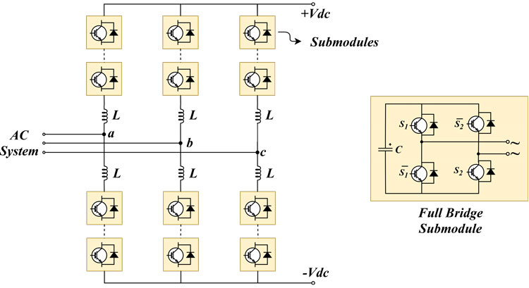

FIGURE 2: MODULAR MULTILEVEL CONVERTER (MMC) WITH FULL-BRIDGE SUBMODULES.
Funding
This project has received funding from the Shift2Rail Joint Undertaking (JU) under grant agreement No 826238. The JU receives support from the European Union’s (EU) Horizon 2020 research and innovation programme and the Shift2Rail JU members, other than the Union.


Issue
Related topics
Related organisations
Birmingham Centre for Railway Research and Education (BCRRE)


