FLEXXSpeed Bogies for ZEFIRO 380 – the new very high-speed train for China
Posted: 17 September 2010 | | 1 comment
In the 1950s and 1960s, specific programmes were initiated to increase service speeds on rail. In Europe and Japan especially, these efforts lead to a considerable increase in the attractiveness for long-distance travellers to choose rail instead of air or road transportation through shortening journey times.
In the 1950s and 1960s, specific programmes were initiated to increase service speeds on rail. In Europe and Japan especially, these efforts lead to a considerable increase in the attractiveness for long-distance travellers to choose rail instead of air or road transportation through shortening journey times.
In the 1950s and 1960s, specific programmes were initiated to increase service speeds on rail. In Europe and Japan especially, these efforts lead to a considerable increase in the attractiveness for long-distance travellers to choose rail instead of air or road transportation through shortening journey times.
China faces large distances between cities and tremendous economical growth, resulting in an increasing need for transportation over long distances. Therefore, investment in high-speed rail has political priority in China. Within the next three years, China will operate 13,000km of high-speed lines, making it the largest high-speed railway network in the world.
Right from the start, Bombardier was a strong partner in the development of highspeed rail in China. Bombardier has the strongest track records for high-speed bogies worldwide, its history of high-speed dates back into the very early years of the 20th century. A significant step in high-speed rail technology worldwide was the development of the very high-speed trains in Germany. In 1965, for the first time in Europe, a train was operated at 200km/h in ordinary passenger service with Bombardier bogies. The very high-speed trains in Germany started full-range operations in 1991 with a 280km/h capability; again the trains’ bogies were developed and manufactured by Bombardier.
Since the 1980s, Bombardier has delivered more than 10,000 high-speed bogies operating within Europe, North America and China, with approximately 3,500 bogies for speeds over 250km/h. Bombardier has been a key player in the design and delivery of almost all recent major European very high-speed trains as well as in other significant international high-speed projects. The wide range of Bombardier’s high-speed bogie portfolio reflects this fact.
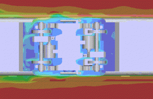

Figure 1 Motorised bogies bottom view (aerodynamic investigation)
In collaboration with its joint venture, Bombardier has produced and put into service more than 1,300 bogies for 80 high-speed trains of the type CRH1 for the Chinese market. Based on that experience, the Chinese Ministry of Railways decided to place an order for 80 trains of the new ZEFIRO 380 with 2,240 bogies.
The new FLEXX Speed Bogies for ZEFIRO 380
General design approach and main technical data As described above, a lot of bogie types for high-speed and very high-speed are available in Bombardier’s portfolio. The approach for ZEFIRO 380 was to analyse the existing bogies and carry over the proven design solutions as much as possible. On the other hand, it is clear that we step in to an area where existing experiences are limited. An operating speed of 380km/h is not really established yet in the world. Therefore, a dedicated design review process with internal and external experts was initiated right from the beginning.
Another aspect of the design approach was to follow the platform idea.
Main technical data:
- vmax = 380km/h (420km/h testing speed)
- Wheelbase = 2.7m
- Wheel diameter new/worn = 920mm/850mm
- Maximum axle load = 18 t
- Nominal power of traction motor = 612 kW
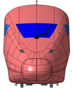

Figure 2 Vehicle front view; bogies well integrated in vehicle shape
Challenges
Obviously, the required top operating speed is the main challenge. Each component needs to be designed and validated for 380km/h respectively for the test speed of 420km/h. But, as one who is familiar with bogie design knows, optimisation on only a component level is not sufficient. The whole bogie concept and its integration within the vehicle needs to be optimised. In other words, finding the best compromise of all the performance requirements – which are very often conflictive – is the key. Here are some concrete examples of this.
The higher the speed, the higher the acceleration/vibration level for components. The higher the component weight (especially the non suspended parts) the higher the acceleration. So it is beneficial to keep the unsuspended mass on a low level in order to stay within the allowed limit for dynamic wheel forces. On the other hand, top speed ‘produces’ a very high annual mileage of about 1 million km. This goes along with a huge number of load cycles for components, which needs to be considered in defining the permissible stress level.
Another area is aerodynamics. Knowing that aerodynamic resistance is growing with the square of velocity and that aerodynamic resistance is – in the case of high-speed/very high-speed trains – the biggest portion of the whole motion resistance of a railway vehicle, it becomes clear that special attention in bogie design is even required in this field. The bottom and sides of the bogie are especially relevant. So it was decided to create a flat and almost closed bogie frame structure at the bottom in order to avoid significant pressure differences. Keeping maintenance requirements in mind was a challenge here.
As mentioned, we optimised the bogie sides for aerodynamic reasons as well. In essence it means the number of yaw dampers was reduced to two and the remaining parts were shifted as much as possible towards the bogie centre. Thermal loads were investigated as well as aero-acoustic aspects.
Bogie architecture and technical features
The overall bogie architecture is shown in Figures 3 and 4.
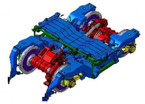

Figure 3 Motorised bogie
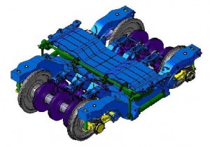

Figure 4 Trailer bogie
Both bogie types have H-shaped frames. The interface to the carbody is realised by means of a traverse beam which ensures an easy and fast connecting/disconnecting procedure. Whilst the motorised bogie uses wheel mounted brake discs, the trailer bogie is equipped with axle mounted brake discs. A considerable number of components are identical on both bogie types, such as the traverse beam, side frames, axle guidance, axle bearings, dampers and traction linkage.
The mounting of the motor is realised in a way to ensure the needed decoupling of motor mass movements from the movement of other primary sprung elements. The positive effect is a reduction of the moment of inertia around the vertical axis, which is beneficial for a stable bogie run on top speeds.
The axle guidance is realised by means of a swing arm as part of the bearing housing. The axle bearing housing was designed consciously as non-split in order to provide a stiff surrounding construction for the bearing, ensuring a proper load zone for the rollers.
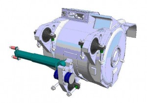

Figure 5 Motor installation
A traction rod transmits longitudinal forces between the bogie and carbody. The rod is mounted via an adapter between the bogie frame and the lower part of the traverse beam.
The bogies are also equipped with a monitoring device, so an instability monitoring system is installed on each bogie. Because of redundancy, two boxes are mounted on the side frame ends of each bogie. The detection algorithm is based on the TSI standard, in which a lateral acceleration of 8m/s2 between 3 Hz and 9 Hz for more than 10 consecutive cycles is considered as instability of the bogie.
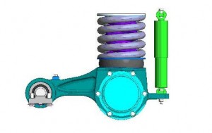

Figure 6 Axle guidance
Validation process
Product validation is essential, specifically for FLEXX Speed 380 bogies since – as mentioned – we move with this application in an area outside of existing operational experiences. A 4-level-programme is foreseen.
Component level
Each new developed/modified component will be tested on its own in order to ensure performance and endurance are guaranteed.
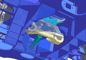

Figure 7 Traction linkage
Bogie level
The bogies will be tested on a roller rig (as available in our premises in Siegen) in order to reveal possible existing vibration phenomena.
Car Level
A car with two bogies (a trailer and a motorised one) will be put on a roller rig in China at Chengdu University. The aim is to determine the dynamic behaviour of the vehicle under defined track conditions, up to speeds of 420km/h. Failure modes, such as malfunction of yaw damper(s), will also be analysed. The aim of the test is to verify the dynamic behaviour of the vehicle with special focus on the interaction of the car body and bogie.
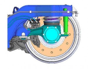

Figure 8 IMS box
Train level
Of course, all tests defined in standards such as EN 14363 for running dynamics or EN 13749 for bogie structure will be performed as well.
Outlook
The newly designed FLEXX Speed 380 bogies for China are seen as the launch application. During the design phase potential future opportunities e.g. in Europe, were also kept in mind. Therefore, features such as Active Lateral Suspension (ALS) or Condition Based Maintenance (CBM) were considered, to possibly be incorporated in future bogies of the FLEXX Speed platform.
About the Authors
Heiko Mannsbarth
Heiko Mannsbarth is Chief Engineer & Product Manager for Mainline and Metro Bogies. He has a degree in Mechanical Engineering (branch: railway technology) and has an Executive MBA. Since 1993, he has been with Bombardier. Before he took over his current job he worked as a Project Engineer and was Head of the Bogie Design Department in Aachen until 2003.
Dipl.-Ing. Jürgen Jakob
Dipl.-Ing. Jürgen Jakob is Director for Marketing and Sales in the Business Unit Bogie of Bombardier Transportation. He graduated from the Technical University of Rhineland-Westphalia in Aachen/ Aix-la-Chapelle, Germany, in Mechanical Engineering and started his industrial career in 1985 as engineer of freight cars and freight car bogies for the rolling stock company Talbot, today Bombardier Transportation. From 1988 he was responsible for development and engineering of passenger coach bogies and from 1995 he held management positions such as Product Line Director Bogies and Technical Sales Key Account for trains in Scandinavia.



I am planning to perform dynamic simulation for a high speed train set. This is for rail vehicle dynamics research.
Any help or idea how can I get the information in constructing such a model? These information include: Body masses, dimensions, stiffness, damping.
I respect any proprietorship. I will make the final mathematical modeling and any simulation results free of charge.
Thanks in advance, JRS