The mechatronic bogie – a novel design
Posted: 3 November 2005 | | No comments yet
Conventional bogie designs suffer from a fundamental conflict of contradicting requirements: Either they are running stable at high speed, but are by no means track friendly when negotiating curves due to their stiff wheel set guidance, or they are able to smoothly follow curved tracks through radial orientation of the wheel sets, but due to the soft wheel set guidance their running stability is limited to fairly low speed.
Conventional bogie designs suffer from a fundamental conflict of contradicting requirements: Either they are running stable at high speed, but are by no means track friendly when negotiating curves due to their stiff wheel set guidance, or they are able to smoothly follow curved tracks through radial orientation of the wheel sets, but due to the soft wheel set guidance their running stability is limited to fairly low speed.
Conventional bogie designs suffer from a fundamental conflict of contradicting requirements: Either they are running stable at high speed, but are by no means track friendly when negotiating curves due to their stiff wheel set guidance, or they are able to smoothly follow curved tracks through radial orientation of the wheel sets, but due to the soft wheel set guidance their running stability is limited to fairly low speed.
Beyond that, stability is influenced by the wheel and rail profiles, the inclination with which the rails are mounted, and the actual gauge, resulting in the so-called ‘equivalent conicity’. Since these parameters differ, for example, between the railway networks of France and Germany, high-speed trains running at full speed on their ‘own’ national network have to observe speed restrictions after crossing the border.
The Mechatronic bogie
These traditional problems are solved with Bombardier Transportation’s ‘Mechatronic Bogie’, a novel design incorporating an active system for stabilisation and radial steering of a bogie’s wheel sets. The underlying mechatronic approach is a holistic philosophy distributing a system’s tasks optimally between mechanics and electronics. It aims at reducing the mechanics of a system to the minimum requirement for its proper function of transmitting forces, while everything regarding reaction, adaptation and adjustment are done by electrically powered actuators and sensor-based control electronics, thus avoiding traditional cumbersome lever mechanisms. Our approach even goes beyond that: The ‘Plug & Play’ architecture of the electronics will avoid any adjustment work of maintenance staff through self-adaptation of the system when modules or elements, i.e. sensors, have been exchanged.
Active Radial Steering & Stability Control
At the heart of the Mechatronic Bogie is ARS – a mechatronic system for Active Radial steering and Stability control.
It comprises one highly dynamic actuator per wheel set, sensorics for detecting the momentary movement of the respective wheel set and a control logic engaging the actuator of each wheel set individually. Stability control is working by counteracting each lateral movement of the wheel set, which is caused by some track irregularity or harmonic movement (sinusoidal run), with an opposed movement. Hence no instability can pile-up, but the wheel set is kept in calm.
Since instability is a highly dynamic process, stability control is acting at higher frequencies up to about 15 Hz. In order to bridge the gap between stability and curve-friendliness, the actuation system has to allow the wheel set to follow a curved track, i.e. to align in radial direction at every spot.
This is done by the second control mode, acting at low frequencies and being superimposed with the high-frequency stability control. The benefits of ARS are manifold:
- Full high-speed performance, i.e. stability up to 400 kph, on different tracks, providing true interoperability
- Strongly reduced wear of wheels and rails and considerably reduced lateral track forces through curve friendly alignment of the wheel sets
- Redundancy and hence omission of passive stabilization means like yaw dampers, which are perfect transmission elements of body noise and vibrations, leading to higher ride comfort at reduced noise insulation effort
- Reduction in vehicle mass due to the omission of mechanical elements
- Reduced track access fees. Modern track access charge schemes take into account the impact of a vehicle onto the track network, hence they give a financial benefit to a vehicle running unrivalled smoothly through application of ARS
In its present configuration, ARS is implemented by using an electrical brush-less motor as actuator – mounted in transverse direction – which is followed by a reduction gear and a unilateral steering rod, moving the wheel set’s axle box on the side of the actuator in longitudinal direction, while the opposite axle box is longitudinally fixed (Figure 1). The slight asymmetry of this arrangement’s kinematics is easily compensated by the controller.Other actuation principles are under investigation and the final selection for a series implementation will be based on the following ranking criteria:
- Reliability in the harsh environment of railway bogies
- Cost – investment, operation and maintenance, i.e. full LCC – in comparison to the reached benefit
- Power consumption
- Simplicity of the arrangement
The prototype implementation of the Mechatronic Bogie with ARS has for the first time been tested in summer 2002 on the full scale roller test rig of Deutsche Bahn in Munich (Figure 3). Its bogie (Figure 2) has been derived from the series trailer bogie of the German VT612 tilting train with passively self-steering cross-linked wheel sets. Equipped with an improved controller version, the test vehicle reached a top speed of 400kph (equalling the limit of the test rig) at full active stability on the roller rig in December 2003 – the basic VT612 design being certified for 160kph only! These trials included numerous investigations of malfunctions, delivering substantial data for the safety analysis of ARS according to the CENELEC standards 50 126 to 50 129.
Figure 4b shows the ‘stability chart’ of the Mechatronic Bogie with ARS in comparison to the passive mode (Figure 4a). Each individual plot shows the reaction of a wheel set when being hit by a lateral ‘step’ of the rail, realised as a sudden lateral displacement of one of the rollers, which are simulating the rails on the test rig by 7.5mm. This graph is displayed for numerous combinations of equivalent conicity of the wheel set and rail pairing and the running speed. As can clearly be seen, the number of excited vibration cycles rises in case of the passive bogie both with increased speed and conicity until the dynamic movement doesn’t fade-out any more. These latter plots define the stability limit of the passive bogie, beyond which the bogie is running unstable. In contrast, the active stabilisation of ARS suppresses the initiated vibration immediately at all speeds and conicities of this set.
The UIC leaflet 518 defines the stability limit as a stair function giving speed limits which have to be reached for each step of equivalent conicity. Figure 5 displays (in red) this UIC limit in comparison to test results gained with different versions of the stability controller. The curve of the optimal controllerlies well above the UIC prescription for the lateral step tests.
Test runs using recorded data of track irregularities as an excitation of the rollers supporting the Mechatronic Bogie are shown in figure 6. At higher conicities the required limits are not completely met due to the suboptimal mechanical design of the prototype bogie. Nevertheless, the mechatronic exhibits excellent behaviour also in these tests.
Comprehensive test runs of the Mechatronic Bogie, mounted under a measurement tilting train rented from Deutsche Bahn (Figure 7), on real track at the private railway test center in Wegberg-Wildenrath (to the west of Duesseldorf) in spring 2004 proved the proper function of the curving controller at cant deficiency up to 2.2 m/s2. During this test campaign the influence of rail switches could be investigated, which turned-out not to irritate the robust controller by any means. Several test runs on tracks with different curve radii and with the Mechatronic Bogie in leading and trailing position were performed to assess the various controller versions and to gain additional information about the system’s behaviour in case of malfunction. These findings resulted in a controller and system optimisation.
Presently, a Swedish Regina train is under modification for tests starting on public track network in Sweden early in the summer of 2006. The top speed will be 250kph plus 10% for certification. In this case motor bogies will be equipped with ARS and the actuators will have to bear tractive and braking forces too; hence a stronger version of the actuator will be applied. These trials, which encompass reliability and winter tests too, will form the final hurdle to be passed in order to gain certification for series development of Bombardier Transportation’s Mechatronic Bogie aiming at regular passenger service. This is expected for 2008.
Thus mechatronics, which is a well-known technology in consumer electronics, robotics and aerospace ndustry (fly-by-wire) will have found its way into the railway business.
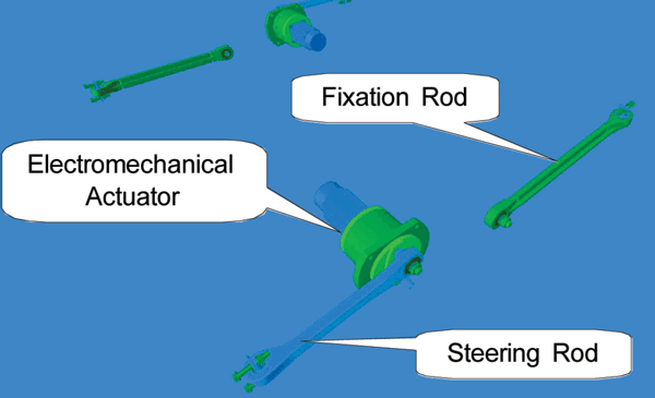

Figure 1: ARS actuation arrangement


Figure 2: Prototype of if the Mechatronic bogie
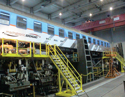

Figure 3: Test vehicle with the Mechatronic bogie on top of DB's roller rig in Munich
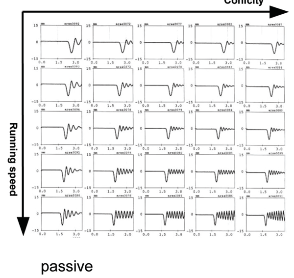

Figure 4: Stability chart of the passive bogie
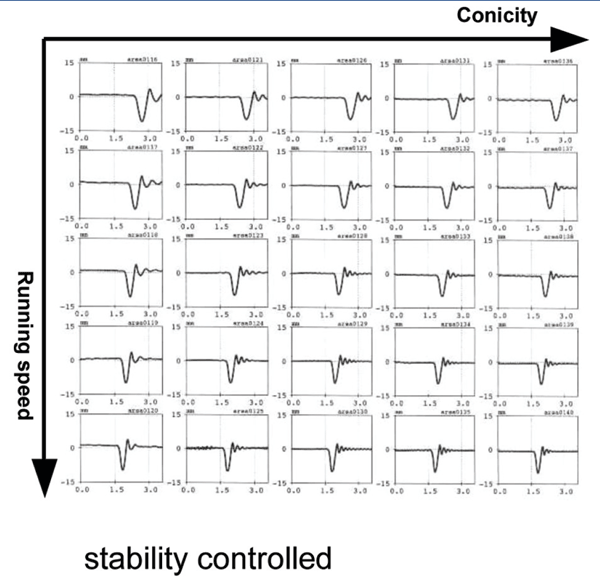

Figure 4b: Stability chart of the Mechatronic bogie with active stability control
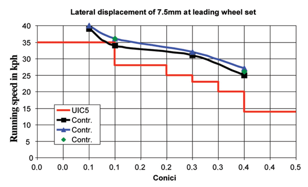

Figure 5: Stability at step excitation
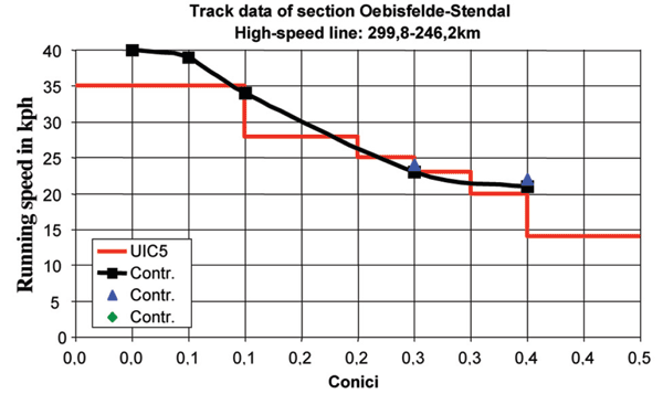

Figure 6: Stability at track irregularities
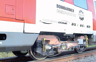

Figure 7: Mechatronic bogie under the test train at the private test centre in Wegberg- Widenrath
OUT NOW: The Definitive Guide to Rail’s Digital Future
The rail industry is undergoing a digital revolution, and you need to be ready. We have released our latest market report, “Track Insight: Digitalisation.”
This is not just another report; it’s your comprehensive guide to understanding and leveraging the profound technological shifts reshaping our industry. We move beyond the buzzwords to show you the tangible realities of AI, IoT, and advanced data analytics in rail.
Discover how to:
- Optimise operations and maintenance with real-time insights.
- Enhance passenger services through seamless, high-speed connectivity.
- Leverage technologies like LEO satellites to improve safety and efficiency.
Featuring expert analysis from leaders at Nomad Digital, Lucchini RS, Bentley Systems and more, this is a must-read for any rail professional.


