Machines and technology for high-capacity lines
Posted: 3 April 2006 | | No comments yet
Whenever the speed or capacity of a line is increased or a new line is built, the application of appropriate track maintenance and upgrading procedures is very important to enable optimal and efficient use of the lines. In addition to that, a high level of comfort and safety has to be maintained on high-capacity lines.
Track maintenance technologies are developed continuously in order to meet the demands of high performance rail traffic. Investment in high-tech machines with high-tech units is worthwhile. The output of the machines for track laying and maintenance is far greater than ever before and intelligent control circuits are being used increasingly. This has decisive effects on the work result and on the cost-effective performance of the operations. The focus is always on the long-term effect of a maintenance operation and at the same time optimisation of the costs. Cheap methods, which do not fulfil these demands, cause follow-up costs not only for the operating department but also for the maintenance department which far exceed the original savings.
High-speed traffic
Characteristics of high-speed lines
High-speed traffic provides a fast link between conurbations. It is characterised on the one hand by the maximum speed, but it is more important to maintain a constant high speed over the main part of the route. On upgraded lines this can often only be achieved by applying tilting train technology.
Generally high-speed traffic is divided into three categories:
- Speeds up to 200 kph
- Speeds from >200 to 300 kph
- Very high speeds over 300 kph
During a 24 hour day, high-speed lines very often have only certain periods with very dense passenger traffic so that windows for additional freight traffic are available.
The permanent way for such routes must have a precise geometry, keeping the very narrow tolerances in the millimetre range. Routes for tilting trains also require exact compliance of the geometry of the transition curves to avoid maladjustment of the coach body inclination. In spite of these high demands on the track, it has to be constructed and maintained at low cost to safeguard the competitiveness with other traffic carriers. Although alternative track designs such as paved track have been developed, the predominant part of the high-speed routes is today furnished with ballasted railway track. The construction and maintenance methods for that were optimised many years ago. With regard to the life-cycle costs, the modern ballasted railway track is also a very economical solution.
Interaction of track and rolling stock
Track faults of different wavelengths stimulate the car bodies with different frequencies. Frequencies between 0.5 and 10 Hz are regarded as critical for the rolling stock. At lower speeds these frequencies are caused by short wave errors, therefore it is sufficient to correct the track in smoothing manner. At higher speeds faults in track geometry with larger wavelengths also cause considerable dynamic forces and must therefore be eliminated. Figure 1 shows that wavelengths of up to 100 ms must be considered at speeds of 160 kph, at 350 kph even 200 m long faults cause rolling stock reactions . This theoretical survey coincides with the practical experience of high-speed operators and has recently caused a change in the track maintenance strategy of some railways – changing from smoothing mode to absolute track geometry.
Absolute track geometry
On high-speed lines deviations of track geometry from the target position have to be kept to a minimum. High-speed railways therefore use absolute reference systems for track geometry.
Austria, Germany
With the introduction of combined levelling, lining and tamping machines in 1960, the general trend was to carry out smoothing track correction only. It soon happened that the tracks moved away from the original position and transition points were shifted. This resulted in a loss of ride comfort and increased rail stresses. From 1972 onwards, therefore, fixed reference points were established on monuments or catenary masts in Austria and Germany. The position of the track is defined in relation to the fixed points and the versines in between (figure 2), the target values are saved in the general track data base. Other railways such as Network Rail (GB), SNCF (France) and SBB (Switzerland) introduced similar systems.
Track maintenance
The necessary maintenance must be ensured on high-capacity tracks, the same as for any other production plant. Breaks in production for maintenance of catenary, signalling installations, rails and fastenings and the track geometry should be scheduled so that the customer does not change to other traffic carriers due to unexpected production breakdowns or delays. In these production breaks, it is of course advisable to bundle the various maintenance jobs to be performed.
New tracks must be serviced accordingly from the outset. Neglect of the maintenance in the initial phase of service life will cause inherent failures that cannot be compensated later.
New technologies
Track maintenance technologies are further developed continually in order to meet the requirements of high-capacity rail traffic. It is worthwhile investing in high-tech machines with sophisticated work units. Machines for track maintenance have become more efficient and are increasingly equipped with intelligent controls. This has decisive effects on the work results and on the cost-efficient performance of the tasks. Together with optimisation of the costs, the long-term effect of a maintenance operation stands at the forefront.
Some of the latest developments and trends are:
Track surveying
Before any efficient and precise track maintenance work can be carried out, a track survey of the actual geometry has to be done, measuring the longitudinal level and alignment of the track. In the past extensive manual track surveying using sighting instruments was involved for this job.
If the track is to be restored to design geometry or given a new design, the data of the data base must be made available in the track.
The EM-SAT (Figure 3) track survey car enables fully mechanised measurement of the actual track geometry using a laser reference chord. It consists of a main machine with the computer system and the laser receiver and an auxiliary trolley (‘satellite‘) which carries the laser transmitter. Measurements are taken in a cyclic sequence: the machine moves forward along the laser beam and deviations from the target geometry are measured and recorded. It stops every 50 to 150 ms at a fixed point and then the laser satellite trolley is moved forward again. The working speed of the machine is 8 kph, while the average measuring speed (including all stops) is 2.5 kph and, besides the displacement and lifting values, superelevation and gauge faults can also be measured.
The recorded data and the calculated correction values are displayed on the computer screen in a similar manner as on the ALC screen of the Tamping machine computer and can be reprocessed on-board or off-board as required. Electronic transmission of data to a tamping machine equipped with the ALC automatic guiding computer guarantees highest precision and at the same time prevents any transmission faults which can occur in manual measuring.
The experience of DB-AG (German Railway) is: accuracy to 1 mm, measuring speed of 1.5 to 2.6 kph and a cost reduction of EURO 3.- per m of measured track.
The EM-SAT not only performs a track geometry survey when preparing for tamping of the track, it is also operated on track relaying and rehabilitation sites and for the acceptance of newly built tracks. The EM-SAT can also be used to establish a track geometry data base where these data are unknown.
Satellite-assisted track surveying
Maintaining the fixed points is labour intensive and therefore quite costly. Furthermore, when checking their position it is often found that their position has changed in the range of several centims. The manual measurement of the track position in relation to the reference points slows down the measuring speed and is also a source of inaccuracy and further costs.
For laying new lines and for surveying existing lines with regard to their general layout, the application of the satellite-supported Global Positioning System is already standard technology. The latest development now is the combined use of EM-SAT and GPS (figure 4) to check the track geometry.
Incorporation of ballast profile measurement
Additionally the EM-SAT can be equipped with a non-contact ballast profile measuring system. In the course of track surveying the system determines the ballast situation accurately together with the lifting values.
The system records the ballast profile by means of a laser scanner. When the laser pulse hits the ballast profile, it is reflected and the distance and measuring angle are registered in the receiver of the laser scanner.
The contour of the ballast profile is computed from the sequence of pulses received and stored every 2 m (max. speed 15 kph). On the computer display the measured profile is superimposed by the image of the target profile which the operator selects appropriate to the line before starting work. A surplus (green bars) or a lack of ballast (red bars) is separately indicated for the right and left side of the track (figure 5). This allows the ballast profile to be checked immediately during the measuring run. The recording results, which can be exported onto a floppy-disk or ZIP for an in-depth office evaluation, enable decisions to be made about the lifts to be performed and ballast requirements.
09-4X Dynamic Tamping Express
The maintenance of a track requires a range of work processes that must be coordinated as efficiently as possible. The better the work technologies act together, the higher will be the achievable work output, the quality of work and ultimately the cost-efficiency.
One of the latest machine concepts for high performance tamping machines is the 09-4X Dynamic (figure 6). It incorporates a continuous action 4 sleeper tamping unit paired with two stabilising units on an articulated trailer. Especially for service on high-speed lines the 09-4X Dynamic is an interesting and cost effective alternative to the use of two separate machines. Due to a further increase in overall performance the length of track possessions and their cost can be reduced.
Ballast management
When it is considered that a single kilometre of a conventional double-track line has between 3000 and 5000 m3 of ballast (depending on type of permanent way and track spacing) the absolute necessity for economical handling and management of this valuable asset becomes obvious. Detailed knowledge of the quantities of ballast in the track (see EM-SAT ballast profile measuring) is the first step towards efficient ballast management. Some sections of a track lack ballast while others have a surplus. So the goal is to recover the surplus ballast and add it where it is needed.
The combination of this task with the ballast profiling and distribution work is available. The great advantage of this incorporation compared to the previous method of loading, transportation, distribution, recovering and returning the excess ballast is the saving of time, personnel and equipment, thus achieving a much higher cost efficiency. Two proven machine concepts can be used for this task.
The USP 2010 SWS combines high performance ballast distributing and profiling with a ballast storage capacity of 10 m3. By using an additional trailer it would be possible to integrate a second sweeper brush unit (figure 7).
The other alternative is the BDS – Ballast Distribution System, successfully in operation in the USA on AMTRAK’s and Union Pacific’s track as well as in Latvia (figure 8), Lithuania and Austria. One of the unique features of the BDS is that the ballast storage capacity can be enlarged as required by adding material conveyor and hopper units.
The BDS was introduced in May 1991. As a result AMTRAK was able to reduce its purchase of new ballast by 71% during the remainder of that year, a saving of around US$ 36.000, equivalent to approx. 34.000 t of ballast. Amtrak estimated that the system paid for itself within two years.
Ballast cleaning
A clean, elastic and homogenous ballast bed is an absolute necessity for problem-free functioning of the wheel-on-rail system. This is gaining additional importance particularly on high-speed lines and other high-capacity sections of track.
High-capacity ballast cleaning machines
In order to minimise track occupancy times on major worksites, it is necessary to use high-capacity ballast cleaning machines.
This trend started with the RM 800, successfully proven in operation for numerous years, and was then followed by other machines of the RM 800 series and the machines of the RM 900 series achieving cleaning outputs ranging from 800 to 1,000 m3/h. These machines are capable of keeping up with the performances of track renewal trains, thus accomplishing major worksites in shorter track possession times.
As a further improvement machines were developed capable of taking ballast from MFS material conveyor and hopper units and distributing the ballast in the cleaned track under the machine.
RM 800 Super 3S
The RM 800 Super 3S (figure 9) is a high-capacity ballast cleaning machine with increased output due to the use of three vibrating screen boxes of 1500 m3/hr. The undercutting system has a cardan type cutter bar which enables infinitely variable adjustment of the cutting width.
Ballast cleaning and track relaying machine
The complete renewal of a section of track requires both the cleaning of the ballast bed and the exchange of the skeleton track. According to UIC recommendations this must be performed exactly in the following order: in the first working operation the track ballast is cleaned using a ballast cleaning machine and then the skeleton track is exchanged using a track renewal machine.
Since these two operations can practically never be performed in the same track possession, the track has to be made ready for traffic again after the ballast cleaning using tamping machines or an MDZ mechanised maintenance train to ensure unhindered passage of trains between the two phases of construction. Track renewal is later performed in a second track possession, after which the MDZ will also have to produce the correct final track geometry.
The commercial costs associated with renewal work on this scale are correspondingly high. In addition to the costs for planning, machines and staff, worksite security, etc., there are the respective operational hindrance costs for two complete track possessions to be considered. Nevertheless, this is a generally accepted technology today which has been in use around the world for many years – not least for lack of realistic alternatives.
The combination of ballast cleaning and track renewal in one machine has been under discussion for some time. Certainly, the railway administrations want such a technology because the associated savings potential would be enormous.
RU 800 S – the machine to revolutionise line renewal
Now the answer is here: Plasser & Theurer has designed the RU 800 S, a continuous action ballast bed cleaning and track renewal train. This machine combines the two working operations of ballast bed cleaning and track renewal in one single machine. This makes it possible to perform the renewal of sections of track in only one track possession, with all the associated technological, logistic and above all economic advantages (figure 10).
Conclusion
The continuous development and improvement of track maintenance machines has led to a range of designs for all applications that not only fulfil the high demands of accuracy for high-speed railways but also provide cost-effective solutions, either by increasing the working speed or by implementing technologies that save precious raw material. New high technology machines contribute to the sustainability of the investments in high-capacity passenger lines as they provide a high level of maintenance.


Figure 1: Reaction-oriented evaluation of track geometry
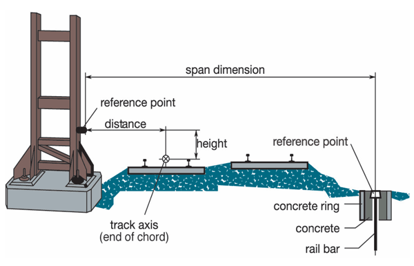

Figure 2: Fixed point system DB, OBB


Figure 3: Network Rail’s Automatic Track Geometry Survey Machine EM-SAT
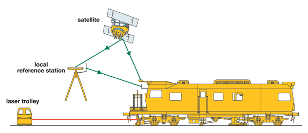

Figure 4: Application of GPS on EM-SAT
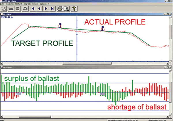

Figure 5: Ballast profile measuring device
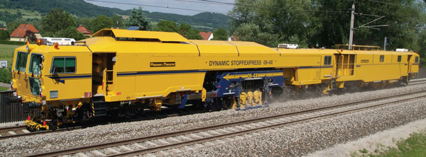

Figure 6: 09-4XDynamic Tamping Express


Figure 7: USP 2010 SWS
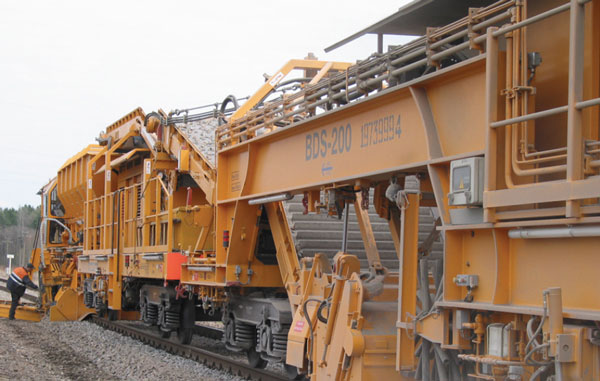

Figure 8: Ballast distribution system operating in Latvia


Figure 9: RM 800 Super 35


Figure 10: Sketch of combined track relaying and ballast cleaning machine
References
- Haigermoser, Dr. Dipl.-Ing., Andreas: Demands of rolling stock on track quality, paper presented to ÖVG working committee track on 2004-11-08
Global Railway Review Autumn/ Winter Issue 2025
Welcome to 2025’s Autumn/ Winter issue of Global Railway Review!
The dynamism of our sector has never been more apparent, driven by technological leaps, evolving societal demands, and an urgent global imperative for sustainable solutions.
>>> Read the issue in full now! <<<


