Bedding optimisation in turnouts
Posted: 26 November 2007 | | No comments yet
Geometrical discontinuities along turnouts can lead to strong localised variations of superstructure loads. By using Under Sleeper Pads (USP) with varying stiffness, the bedding conditions can be optimised and as a result the turnout area can be smoothed out. Modern railway tracks need to be able to bear the loads from rail vehicles via the rails, rail seats and sleepers as evenly as possible and distribute such to the track superstructure and subgrade. By distributing these loads sufficiently, stresses on the superstructure elements can be kept as low as possible, helping to minimise maintenance expenses and thus increase the operating life of the track system.
Geometrical discontinuities along turnouts can lead to strong localised variations of superstructure loads. By using Under Sleeper Pads (USP) with varying stiffness, the bedding conditions can be optimised and as a result the turnout area can be smoothed out. Modern railway tracks need to be able to bear the loads from rail vehicles via the rails, rail seats and sleepers as evenly as possible and distribute such to the track superstructure and subgrade. By distributing these loads sufficiently, stresses on the superstructure elements can be kept as low as possible, helping to minimise maintenance expenses and thus increase the operating life of the track system.
Geometrical discontinuities along turnouts can lead to strong localised variations of superstructure loads. By using Under Sleeper Pads (USP) with varying stiffness, the bedding conditions can be optimised and as a result the turnout area can be smoothed out.
Modern railway tracks need to be able to bear the loads from rail vehicles via the rails, rail seats and sleepers as evenly as possible and distribute such to the track superstructure and subgrade. By distributing these loads sufficiently, stresses on the superstructure elements can be kept as low as possible, helping to minimise maintenance expenses and thus increase the operating life of the track system.
Although one can draw on tried and trusted calculation methods, as per Zimmermann for beams on elastic foundation in respect of the load distribution effect, there are limitations when it comes to turnouts. Due to their geometry alone, turnouts are an irregularity which can result in various degrees of rail deflection within different areas, even if other boundary conditions remain unchanged.
Variations in stiffness along the tongue and frog area, as well as the constantly changing load-bearing surface area of the sleepers in the ballast superstructure result in discontinuity of the track system.
The differences in the load- distributing over the turnout length is a 3-dimensional problem which can be grasped and analysed using Finite Elements Methods (FEM). By installing additional elastic elements with defined stiffness it is possible to increase the load-distributing effect of the rails. At the same time, the load-bearing characteristics of the track frame can be optimised. One cost-effective way of approaching this target is to use Under Sleeper Pads (USP) with varying degrees of stiffness.
The following paragraph describes the fundamental impact of the bedding modulus, the possible increase in superstructure elasticity via USP and a 3-dimensional FEM turnout model for optimising the USP arrangement is provided.
Bedding Modulus
The loads on the track superstructure stemming from rail traffic mainly depend on the behaviour of the track bed, as well as the geometry and stiffness characteristics of the track frame. For traditional ballasted track, the elasticity derives primarily from the flexibility of the ballast bed and the subgrade. It is generally expressed via the bedding modulus C and represents the relationship between the surface pressure and the related rail deflection.
p = pressure between sleeper and ballast [N/mm2]
y = rail deflection [mm]
In simplified terms, the bedding modulus indicates how much pressure in [N/mm2] results in a deflection of 1mm. The bedding modulus of different kinds of ballasted track ranges from roughly 0.05 N/mm3 (very soft) to more than 0.40 N/mm3 (very hard) on average, depending on the installation conditions1. For new rail lines, the higher stiffnesses mainly result from the construction of compacted substructure and anti-frost layers. Moreover, the use of the Dynamic Track Stabilizer (DGS) in ballasted track also results in consolidation. While measures of this kind increase the load-bearing ability of the track bed, at the same time the rail’s function as a load-distributing element is reduced, which can have negative ramifications for dynamic effects in wheel-rail contact and can lead to increased stresses on the ballast.
Higher degrees of bedding stiffness due to consolidated ballast and subgrades with greater load-bearing capacity can be adjusted by installing elastic elements with lower levels of bedding modulus.
With regard to the flexibility of the ballasted track, the resulting bedding modulus of the standard gauge track should be set in a way that sufficient rail deflection is ensured, which should be about 1.2-1.5mm, taking into consideration the load-distributing effect in the track and the turnouts. The limiting factor is generally the maximum permissible amount of rail foot tension.
Increasing superstructure elasticity with Under Sleeper Pads
USPs are a cost-effective method for subsequently increasing the elasticity of the superstructure and reducing wear and tear on the ballast. They are comprised of additional elastic elements located between the sleeper and the ballast and are today available in a continuous range of modulus levels from approximately 0.02 N/mm3 to harder than 0.30 N/mm3 for standard products (determination of bedding modulus as per BN 918 145 – 01 on a prescribed load plate with ballast profile2).
The track frame consisting of the rails and concrete sleepers, which is rigidly connected into a load-bearing structure via the rail fasteners, can remain unchanged in its traditional role. This is also valid for upgrading of tracks, as the costs involved for such work are also comparatively low.
With ballasted track, elastic USPs not only allow for a longer rail bending line, which reduces loads on the ballast, they also help to prevent contact abrasion as the top layer of ballast can become embedded in the pads. Hard contact points between the bottom of the sleeper and the ballast are alleviated and the railtrack mounting is more homogeneous. The pads also help to prevent sudden settling of sleepers due to cavitation3.
Due to stabilisation of the top ballast layer, migration of ballast rocks resulting from dynamic forces is shifted to lower layers, which can have a benign effect on the long-term quality of the superstructure.
Even under the assumption of declining effectiveness over the lifetime of the rail, USPs still cannot result in any detrimental impact on the track superstructure. In this regard, they can be seen as fail-safe elements. The track superstructure will always exhibit more favourable characteristics than structure without any USPs.
There are numerous ways to ensure adequate adhesion of the pads to the sleepers. One possibility is to glue the pad to the cured concrete, but the general trend in the future shows that the pads are integrated directly into the sleepers as a part of the manufacturing process. A tight connection can be achieved using a plastic mesh, half of which is integrated into the sleeper pad and the other half of which can be vibrated into the wet concrete of the sleeper.
Tests in Germany have shown that the use of sleeper pads allows for significantly improved track behaviour and dynamic vibration behaviour compared to traditional ballasted track4. In Austria, turnouts with USP have already been installed since 2002 and measurements have shown a reduction of vibrations in the 40 Hz-50 Hz frequency range. Moreover, substantially less subsidence was found in turnouts with rigid crossing frogs, even compared to constructions with moveable crossing frogs5. The positive experiences with USP in turnouts have led to the development of a standardised design for the Austrian Federal Railways.
FEM turnout model
It is necessary to understand the entire system in order to be able to transpose the positive experiences gained with padded sleepers to applications involving turnouts. And furthermore to balance out the geometrically determined differences in vertical load distribution. The Finite Elements Method (FEM) can help us to grasp this system.
Using FEM and high-performance computers, it is possible to generate a complete turnout with padded sleepers and to perform analyses in respect of its load-bearing functions. In contrast to the classic calculation method according to Zimmermann, there is no need for idealisation by transformation of the entire structure (transverse sleepers in longitudinal sleeper superstructure, resultant stiffness for several elastic levels). But in order to cut calculation times, the individual components are reduced by base elements to their relevant functionality and the necessary degrees of freedom. Another advantage of the model is that variable parameters can be assigned for all geometries and stiffnesses in the rail elements (tongue, crossing frog, check rails, etc.). The same is valid for sleeper parameters and the non-linear behaviour of the rail fasteners (rail plates/baseplates function under pressure loads – fastening clips function under tension loads). Moreover, the behaviour of the bedding (sleeper pads and ballast) can be modelled using any desired non-linear deflection curves.
As the individual elastic levels are not ‘superposed’ by the formation of resultant spring stiffness, it is possible to simulate a division of the flexibility in levels above and below the sleepers. As a result, it is also possible to individually observe deformation variables.
Parameterisation of the model allows for any standard turnout to be generated with the defined characteristics and for calculations to be carried out with a moving load collective, corresponding to the load impact of the bogies. As a result, one obtains all of the vertical deformation in the entire structure (subsidence and rises); the strains result from the kinematic conditions and the parameters of the construction components. A holistic model of this nature can be helpful for grasping the system comprising the elastically mounted turnout in the ballasted track and making targeted adjustments for the further development of such.
Analysis of load-bearing behaviour
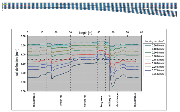
In order to understand the bedding impact on the vertical rail deflection, the stiffness of the ballast and the subgrade throughout the entire turnout area is uniformly and stepwise reduced within the framework of a simulated calculation. The maximum rail deflection can therefore be calculated for each load position, based on the load collective for a typical bogie (axle load 220 kN, 3m spacing). The deflection patterns presented in Figure 1 represent the envelope for the maximum vertical deformations of the relevant rail.
From the curves, one can see that a lowering of the bedding modulus results in an increase in rail deflection as desired. But at the same time, the various differences in the stiffness can also be seen along the path of the turnout. The differences in the deformation curves are magnified. The lower the bedding modulus is – the more pronounced the differences are. In this regard, the amount of deflection is lowest in the crossing frog due to the higher level of rail stiffness and the large surface area of the sleepers, whereas immediately after the last long sleeper.
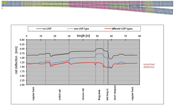
By optimising the arrangement of USPs with varying degrees of stiffness, these differences can be smoothed out. Figure 2 (on page 82) shows a comparison with an improved arrangement of stiffnesses using various types of USP.
The first curve shows as an example of the deflection curve without any additional USPs. The rail deflection of 0.8mm in the regular track results exclusively from the defined bedding modulus of the ballast and subgrade of 0.2 N/mm3. If the vertical deformation is increased by the uniform installation of additional USPs, the resulting bedding modulus of roughly 0.10 N/mm3 leads to an increase in deflection to 1.3mm before and after the turnout. The differences in vertical rail deflection can be smoothed out by the installation of various USPs, in the event of identical initial levels. This allows for a more homogenous pattern of deflection to be achieved (using different USP types). The turnout is smoothed in its function as a load-bearing element.
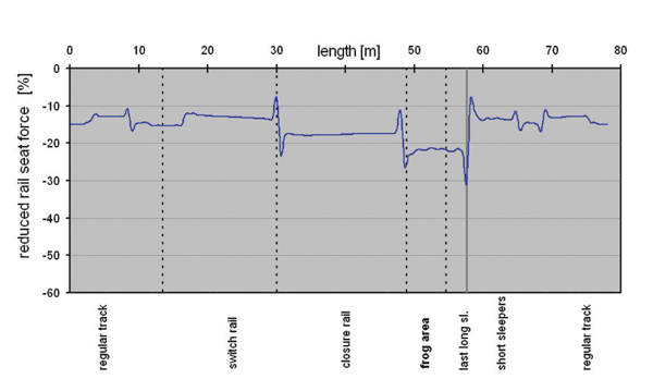
Figure 3 shows the reduction of rail seat forces compared to a turnout without USP. Even with the relatively stiff pads used in this case (> 0.2 N/mm3) the forces transmitted into the superstructure can be reduced on the order of 10% to 30%, depending on the part of the turnout.
Summary
The use of USPs can increase the elasticity of track superstructure with relatively low investment costs. At the same time, the ballast which is a latent source of track instability is stabilised, as individual ballast rocks can become embedded in the surface layer of the USP. Loads on the superstructure are reduced by a more homogenous mounting of the sleepers and track stability is improved.
Moreover, in turnouts, the geometrically determined differences in stiffness can be smoothed out. To achieve this target, USPs with various degrees of stiffness can be used, positioned in a way that the entire construction features improved load-bearing conditions. Track irregularities resulting from turnouts can thus be mitigated and vibrations can be reduced.
Using a turnout model based on the Finite Element Method, it is possible to analyse the load-bearing behaviour of the construction. As data can be varied for different parameters, it is possible to analyse a very wide range of geometric boundary conditions and stiffness conditions. The challenge involved is to take into consideration the non-linear bedding properties.
Using the FEM turnout model, an optimised arrangement of Sylomer® USP can be calculated for any situation.


Figure 1: Deflection pattern of the relevant rail through the entire turnout with stepwise and uniformily reduced bedding modulus


Figure 2: Comparison of rail deflection patterns with optimised solution using USP types along the turnout


Figure 3: Reduction of rail seats forces along the turnout with optimised USP solution
References
- Eisenmann, J. und Rump, R.: Ein Schotteroberbau für hohe Geschwindigkeiten. ETR – Eisenbahntechnische Rundschau 46, (1997), Heft 3, S.99…108.
- DB Systemtechnik: BN 918145-01: Technische Lieferbedingungen – Spannbetonschwellen mit elastischer Sohle – Elastische Schwellensohlen, (Jan. 2004)
- Müller-Boruttau, F., Kleinert, U.: Betonschwellen mit elastischer Sohle, ETR 50 (2001). H3 S. 90-98.
- Leykauf, G., Stahl, W.: Untersuchungen und Erfahrungen mit besohlten Schwellen. EI Der Eisenbahningenieur (55) 6/2004, S. 8-16.
- Schilder, R.: USP Under Sleeper Pads – Ein Bericht über bisherige Erfahrungen, ÖVG Salzburg Congress, Band 65, Sept. 2004


